Optical encoder and electronic equipment

An encoder and optical technology, which is applied in the field of optical encoders, can solve the problems of difficult miniaturization of the encoder module, increased current consumption, and unsuitability for use, and achieve the effect of simplifying electrical wiring and realizing miniaturization

Inactive Publication Date: 2009-01-07
SHARP KK
View PDF4 Cites 7 Cited by
  • Summary
  • Abstract
  • Description
  • Claims
  • Application Information

AI Technical Summary

Problems solved by technology

Therefore, by increasing the frequency of the oscillator, it is possible to cope with a wide range of frequencies, but the current consumption increases, making it unsuitable for use.
[0014] In addition, both documents aim to reduce the total number of wiring by half through signal processing, but counters, pulse modulators, oscillators, etc. are required, synchronization with the output unit is required, and the structure becomes complicated, so for encoders installed Part of the module is difficult to miniaturize

Method used


Image

  • Optical encoder and electronic equipment
  • Optical encoder and electronic equipment
  • Optical encoder and electronic equipment

Examples


no. 1 approach

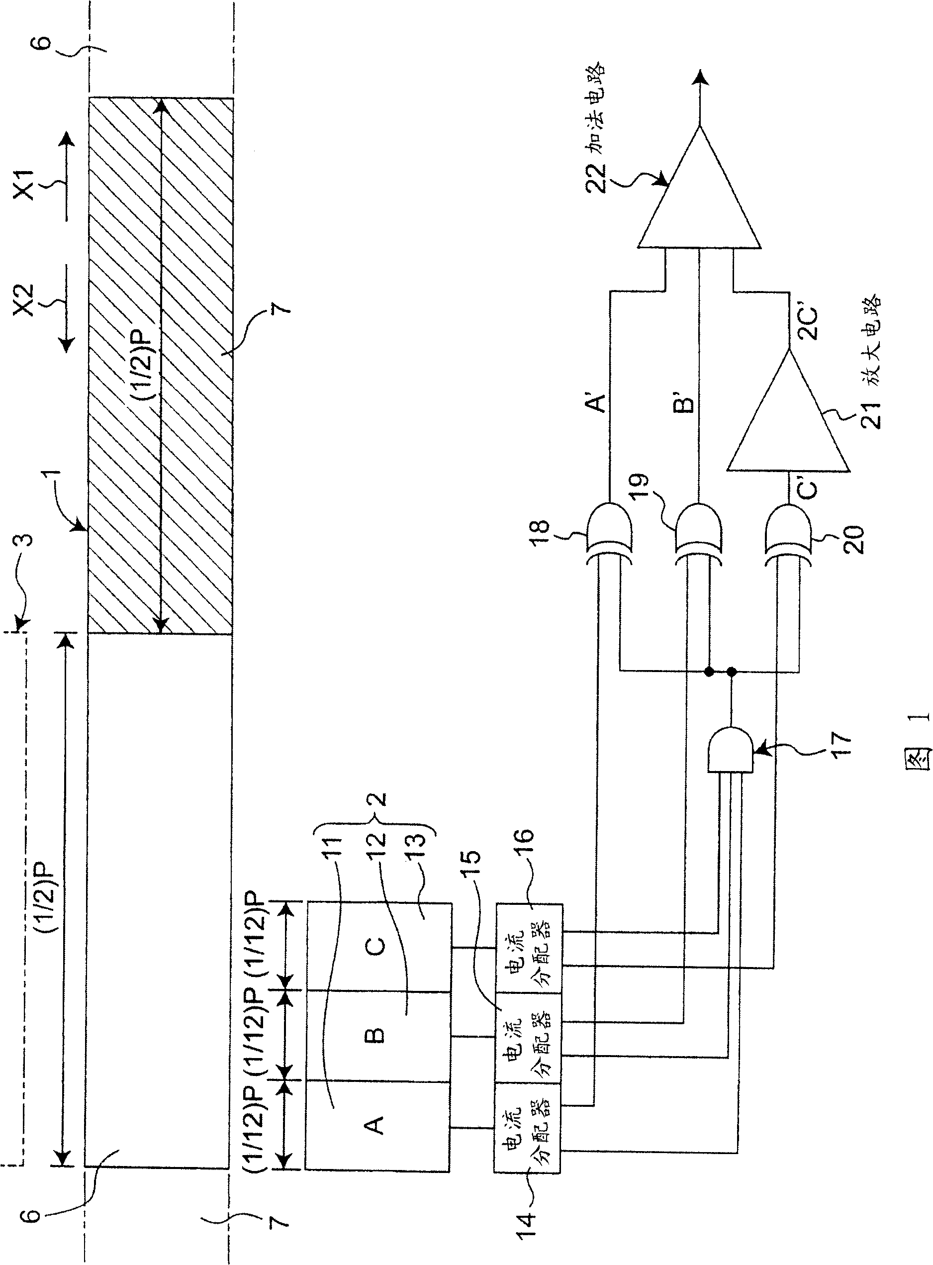
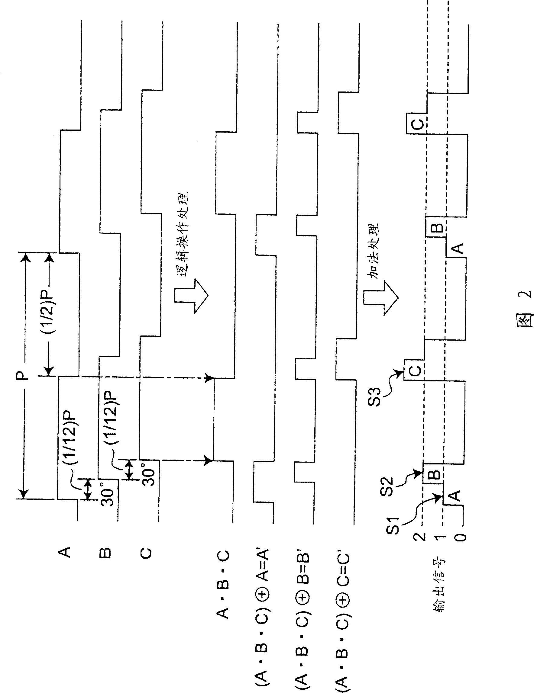
[0067] FIG. 1 shows a first embodiment of an optical encoder of the present invention. This first embodiment includes a moving body 1 , a light receiving unit 2 and a light emitting unit 3 . The light emitting unit 3 is constituted by a light emitting element such as an LED (Light Emitting Diode). The light receiving unit 2 has three light receiving elements 11 to 13 . In addition, the moving body 1 can move in a direction indicated by an arrow X1 or X2, and light-on portions 6 and light-off portions 7 are alternately arranged in the moving direction. If the arrangement pitch of the light-on portions 6 is P, the size (width dimension) in the moving direction of the light-on portions 6 and the light-off portions 7 is (1 / 2)P. The above-mentioned light-on portion 6 passes the light from the light-emitting unit 3 to the light-receiving unit 2 side, and on the other hand, the light-off portion 7 does not pass the light from the light-emitting unit 3 to the light-receiving unit 2 ...

no. 2 approach

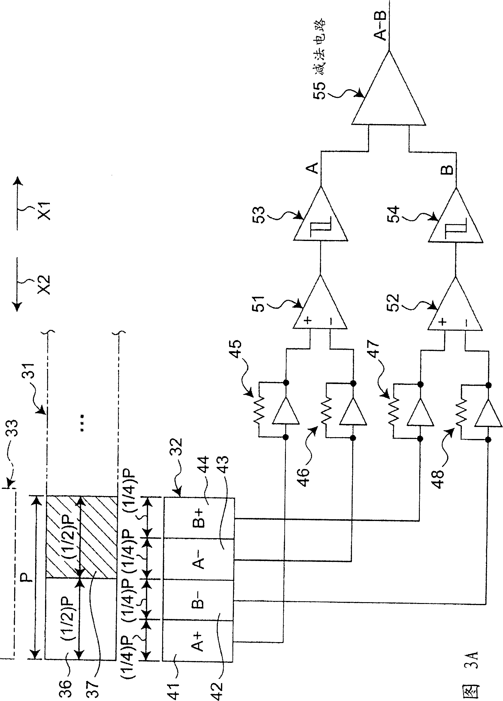
[0074] Next, FIG. 3A shows a second embodiment of the optical encoder of the present invention. This second embodiment includes a moving body 31 , a light receiving unit 32 and a light emitting unit 33 . The light emitting unit 33 is constituted by a light emitting element such as an LED (Light Emitting Diode).

[0075] The light receiving unit 32 has four light receiving elements 41 to 44 . In addition, the moving body 31 can move in the direction indicated by the arrow X1 or X2, and the light-on portions 36 and the light-off portions 37 are alternately arranged in the moving direction. If the arrangement pitch of the light-on portions 36 is P, the size (width dimension) in the moving direction of the light-on portions 36 and the light-off portions 37 is (1 / 2)P. The above-mentioned light-on portion 36 passes light from the light-emitting unit 33 to the light-receiving unit 32 side, and on the other hand, the light-off portion 37 does not pass light from the light-emitting u...

no. 3 approach

[0088] Next, FIG. 5 shows a third embodiment of the optical encoder of the present invention. The third embodiment differs from the second embodiment in that an exclusive OR circuit 61 and an AND circuit are connected between the AD converters 53, 54 and the subtraction circuit 55 of the second embodiment. 62, and a comparison unit 66 is connected to the output terminal of the subtraction circuit 55. Therefore, the third embodiment is the same as the second embodiment in that it includes the movable body 31 , the light receiving unit 32 , the light emitting unit 33 , and the current-voltage converting units 45 to 48 shown in FIG. 3A . Therefore, in this third embodiment, the same reference numerals are given to the same parts as those of the second embodiment, and the description will be given mainly on the parts different from the second embodiment.

[0089] As shown in FIG. 5 , in the third embodiment, the output line 67 of the AD converter 53 and the output line 68 of the ...


PUM


Abstract

This optical encoder includes a light emitting section and a plurality of light receiving elements placed so as to be aligned in one direction in an area where a light beam from the light emitting section may reach. The moving object includes a light-ON section and a light-OFF section. The light receiving element detects movement of the moving object when the light-ON section and the light-OFF section of the moving object pass through a predetermined position corresponding to the light receiving element A light receiving signal processing section receives inputs of a plurality of light receiving signals with different phases from a plurality of the light receiving elements, performs signal processing including at least one signal processing among a logical operation processing, an addition processing, and a subtraction processing on a plurality of the light receiving signals,; and outputs an output signal containing a plurality of signal components which are different in phase and different in signal level with respect to a predetermined threshold level.

Description

technical field [0001] The present invention relates to an optical encoder that uses a light receiving element to detect the position, speed, direction, etc. device. Background technique [0002] Conventionally, an optical encoder has been proposed as an optical encoder in which a plurality of light receiving elements are arranged at intervals of 1 / 4 of the arrangement pitch of the slits in the arrangement direction of the slits of the rotating body, and by The output signals of these light receiving elements are compared to obtain highly reliable rotation information (Japanese Patent Laid-Open No. Sho 59-40258). [0003] In addition, in the optical encoder described in Japanese Patent Laid-Open No. 2005-61896, a method of improving the accuracy of detecting the movement amount of a moving object is adopted by generating and outputting a triangular wave. [0004] In addition, in (Japanese) Unexamined Patent Publication No. 2000-121390, it is disclosed that a phase A signal...

Claims


Application Information

Patent Timeline
Patent Type & Authority Applications(China)
IPC IPC(8): G01D5/36
Inventor 木村直正冈田教和
Owner SHARP KK
Why Eureka
Try Eureka