Magnet coupled resonant type wireless energy transmission equipment having intensifier

A technology of wireless energy transmission and booster, which is applied in the direction of circuit devices, electromagnetic wave systems, electrical components, etc., and can solve problems such as increasing the transmission distance

Inactive Publication Date: 2009-01-07
HARBIN INST OF TECH
View PDF0 Cites 36 Cited by
  • Summary
  • Abstract
  • Description
  • Claims
  • Application Information

AI Technical Summary

Problems solved by technology

Although the existing magnetic coupling resonant wireless energy transmission device has been able to complete the wireless transmission function

Method used


Image

  • Magnet coupled resonant type wireless energy transmission equipment having intensifier
  • Magnet coupled resonant type wireless energy transmission equipment having intensifier
  • Magnet coupled resonant type wireless energy transmission equipment having intensifier

Examples


specific Embodiment approach 1

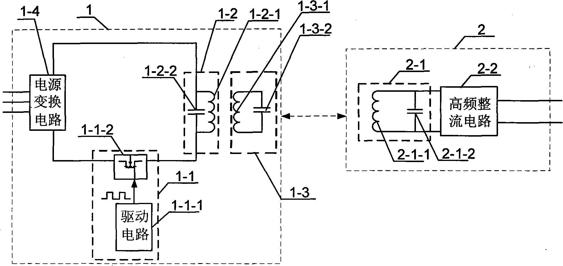
[0015] Specific implementation mode one: combine figure 1 To illustrate this embodiment, the magnetic coupling resonant wireless energy transmission device with a booster in this embodiment is composed of an enhanced transmission source 1 and an energy receiver 2;

[0016] The enhanced emission source 1 is composed of a magnetic field resonance excitation and drive circuit 1-1, a resonant emission circuit 1-2 and a booster 1-3;

[0017] The magnetic field resonance excitation and drive circuit 1-1 is composed of a drive circuit 1-1-1 and a drive switch tube 1-1-2, and the drive circuit 1-1-1 generates a signal that is the same as the set resonant emission frequency or is the resonant emission frequency 1 / n driving signal, drive switch tube 1-1-2 to receive the drive signal; the switching frequency of drive switch tube 1-1-2 is the same as the resonant transmission frequency or 1 / n of the resonant transmission frequency, which is used to switch the DC power supply The energy ...

specific Embodiment approach 2

[0023] Specific implementation mode two: combination figure 1 Describe this embodiment, the difference between this embodiment and the specific embodiment is that one end of the DC power supply is connected to the input end of the magnetic field resonance excitation and driving circuit 1-1, and the output end of the magnetic field resonance excitation and driving circuit 1-1 is connected to the resonant transmitting circuit The input terminal of 1-2, the output terminal of the resonant transmitting circuit 1-2 is connected to the other end of the DC power supply to form a loop; the signal output terminal of the drive circuit 1-1-1 in the magnetic field resonance excitation and drive circuit 1-1 is connected to the drive switch The gate of the tube 1-1-2, the drain of the drive switch tube 1-1-2 is magnetic field resonance excitation and the input end of the drive circuit 1-1, the source of the drive switch tube 1-1-2 is magnetic field resonance excitation and drive Output of ...

specific Embodiment approach 3

[0024] Specific implementation mode three: combination figure 1 Describe this embodiment, the difference between this embodiment and specific embodiment 2 is that the resonant transmitting coil 1-2-1 and the resonant transmitting capacitor 1-2-2 in the resonant transmitting circuit 1-2 are connected in series or in parallel; other components and The connection method is the same as that in the second embodiment.

[0025] The resonant frequency of the resonant transmitting circuit 1-2 is determined by the following formula:

[0026] f = 1 2 π L 1 C 1

[0027] where C 1 It is the capacitance of the resonant emission capacitor 1-2-2. If there are multiple capacitors in the circuit at the same time, it is necessary to calculate the equivalent capacitance acc...


PUM


Abstract

A magnetic coupling resonant wireless energy transmission device provided with an intensifier relates to the field of wireless energy transmission, and aims at intensifying the transmission distance of existing magnetic coupling resonant wireless energy transmission technology. The invented transmission device consists of an intensified emission source and an energy receiver; the two electromagnetic systems with the same specific resonant frequency are used for energy transmission owing to the resonance caused by the same vibration frequency, when the two systems are separated from a certain distance. An intensifier is added in the intensified emission source, strong magnetic coupling is produced between the intensifier and a resonant emission circuit, the intensifier has the functions of reducing impedance, modifying transmitted waveforms, intensifying resonant current, emitting modified alternating magnetic fields outwards, resonance ia produced between the intensifier and the energy receiver. Owing to the adding of the intensifier, the energy transmission distance of the technology is intensified greatly, is about five times longer than the former and is probably even longer.

Description

technical field [0001] The invention relates to the field of wireless energy transmission. Background technique [0002] At present, almost all electrical equipment must use tangible media (such as: using metal wires, wires and cables) as the main connection for power transmission or energy transmission, even for short-distance power transmission (such as computers, TVs, desk lamps, etc.) , It must also go through the cumbersome process of power line connection and laying or pulling wires, so that the placement of electronic and electrical equipment that needs to be powered by electricity is affected. If better wireless energy transmission technology and devices can be developed to achieve effective power transmission that is not affected by foreign objects or the surrounding environment, then the power transmission can be achieved through wireless transmission, then when using these electrical equipment, It must be more handy. In addition, it has very practical applicatio...

Claims


Application Information

Patent Timeline
IPC IPC(8): H02J17/00H02J50/12
Inventor 朱春波张小壮逯仁贵刘凯于春来任立涛
Owner HARBIN INST OF TECH
Why Eureka
Try Eureka