

Control circuit of LED rear-view mirror
A technology for controlling circuits and rear mirrors, applied to electric light sources, electrical components, lighting devices, etc., to achieve the best recognition effect
- Summary
- Abstract
- Description
- Claims
- Application Information
AI Technical Summary
Problems solved by technology
Method used
Image

Examples
Embodiment Construction
[0024] In order to further explain the technical means and effects that the present invention adopts to achieve the intended purpose of the invention, the specific implementation, structure and characteristics of the control circuit of the LED rear-view mirror proposed according to the present invention will be described below in conjunction with the accompanying drawings and preferred embodiments. and its efficacy are described in detail below.
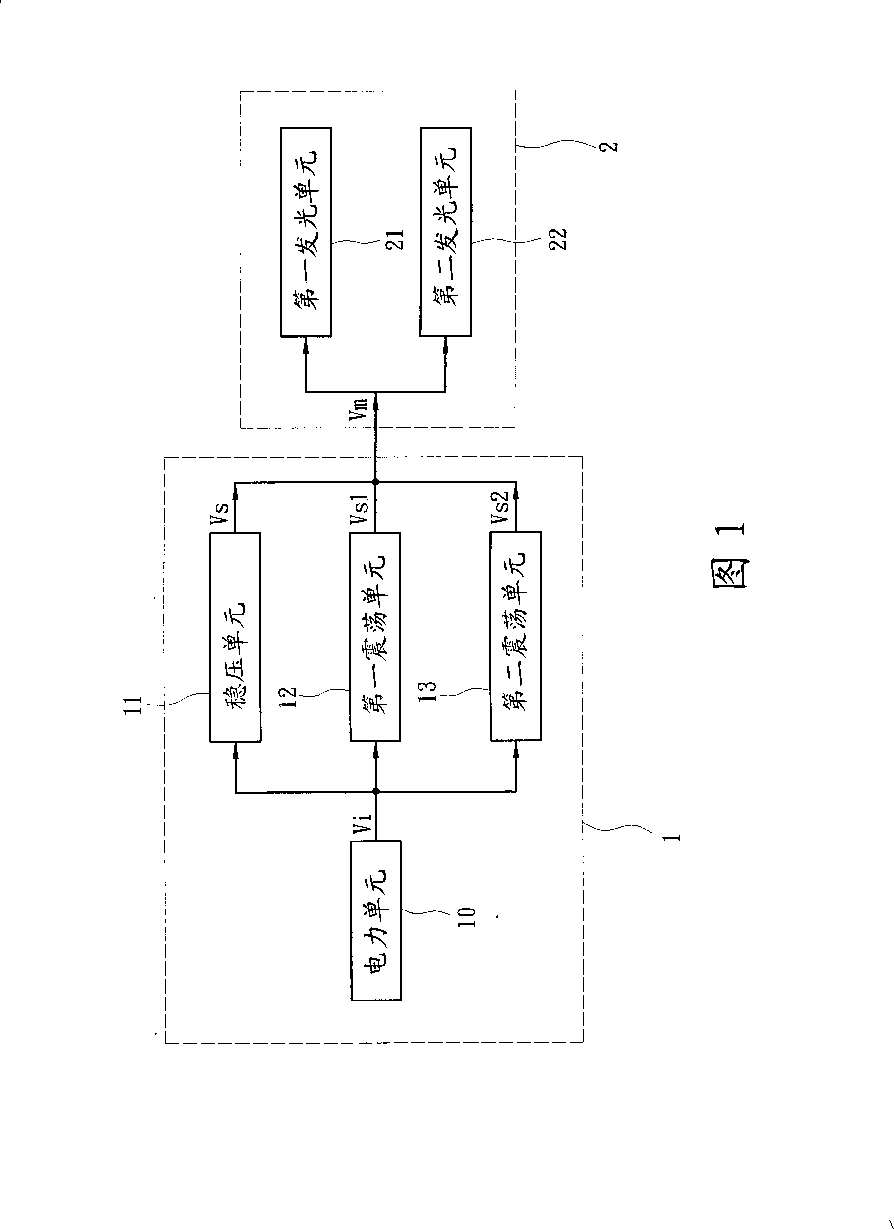
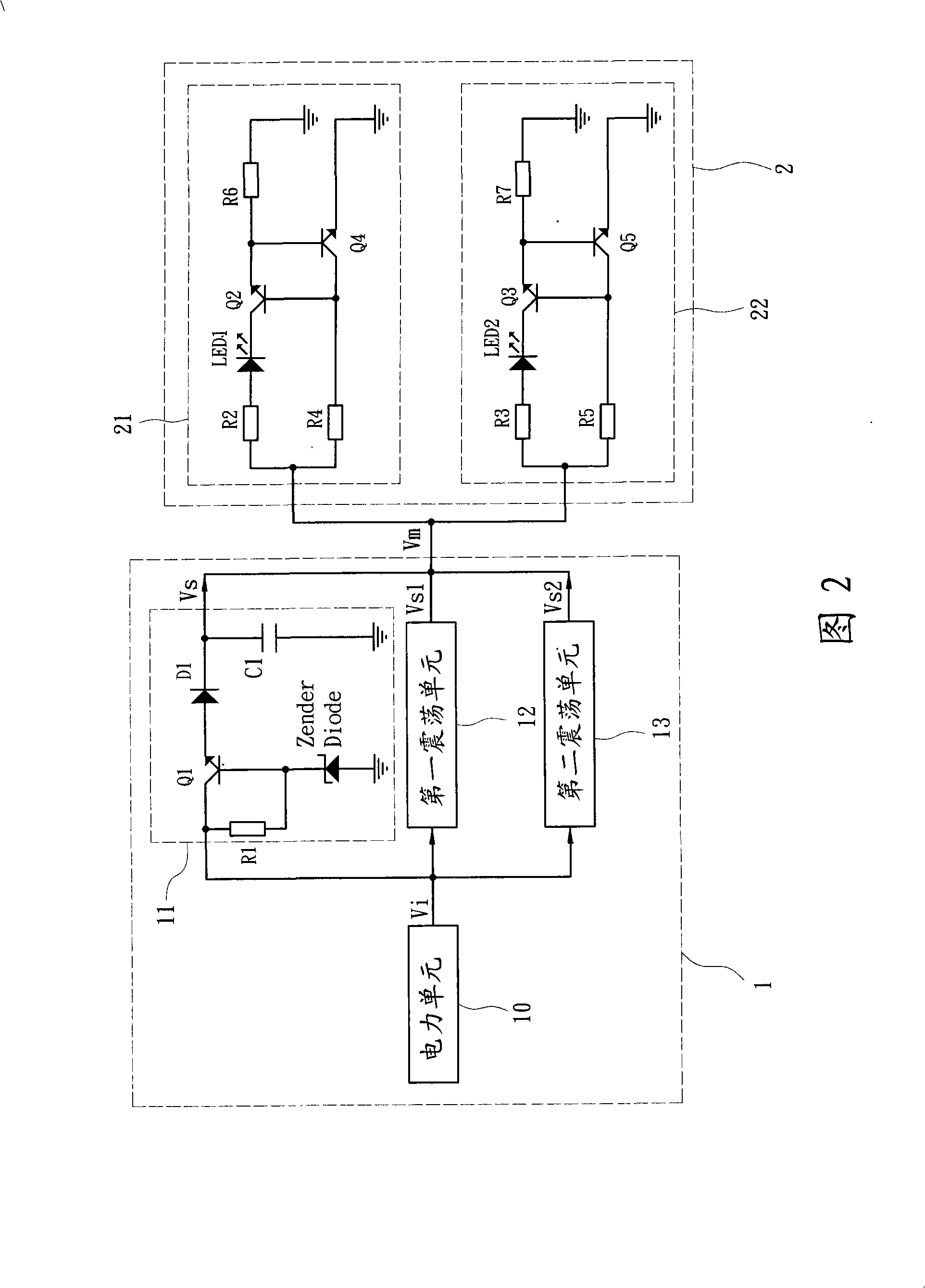
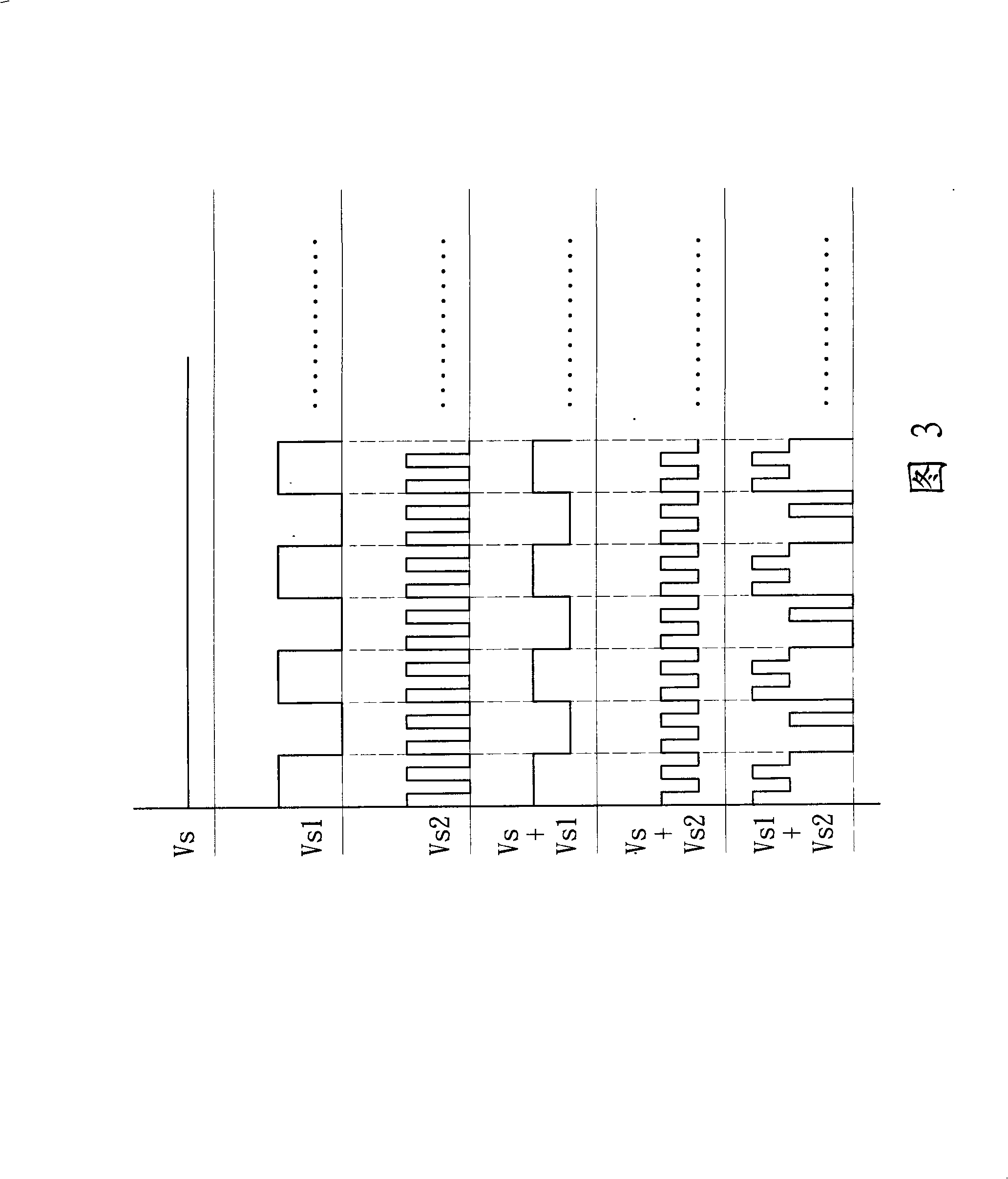
[0025] Please refer to Fig. 1, which is a block diagram of the control circuit of the LED rear mirror of the present invention; A voltage stabilizing unit 11, a first oscillating unit 12 and a second oscillating unit 13 are connected in parallel at the back end of a power unit 10, and the power unit 10 provides an input signal Vi to the voltage stabilizing unit 11 and the first and second oscillating units respectively. The oscillating units 12 and 13 generate regulated signal Vs, first oscillating signal Vs1 and second oscillating s...
PUM
 Abstract
Description
Claims
Application Information