Magnetic induction tomography system and method

A technology of tomography and magnetic induction, applied in the field of magnetic induction tomography system, to achieve high-quality image reconstruction and high spatial resolution

Inactive Publication Date: 2012-07-18
KONINKLIJKE PHILIPS ELECTRONICS NV
View PDF3 Cites 0 Cited by
  • Summary
  • Abstract
  • Description
  • Claims
  • Application Information

AI Technical Summary

Problems solved by technology

This leads to very large, very complex MIT systems
Furthermore, such systems become very expensive due to the required operating equipment

Method used


Image

  • Magnetic induction tomography system and method
  • Magnetic induction tomography system and method
  • Magnetic induction tomography system and method

Examples


Embodiment Construction

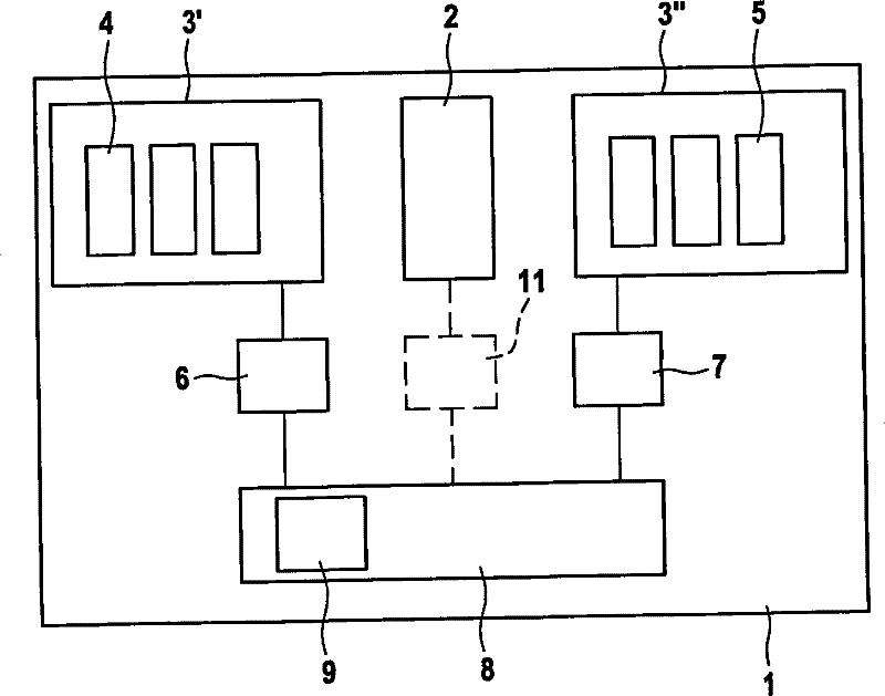
[0039] figure 1 A schematic block diagram of the MIT system 1 according to the present invention is shown. The MIT system 1 is suitable for studying the electromagnetic properties of biological objects, especially conductive tissue 2. The MIT system 1 especially includes a measuring unit 3. The measurement unit 3 includes an excitation module 3'and a receiving module 3". The excitation module 3'includes a power amplifier and a plurality of generator coils 4 adapted to generate a time-varying primary magnetic field, which induces eddy currents in the tissue 2. For this purpose, the alternating current is input into the generator coil 4. The receiving module 3" includes a measuring amplifier and a plurality of sensor coils 5 suitable for sensing the secondary magnetic field, the alternating secondary magnetic field is due to The vortex is generated. The MIT system 1 also includes an electric drive actuator 6 adapted to move one or more generator coils 4 relative to the tissue ...


PUM


Abstract

The present invention relates to a magnetic induction tomography system and method for studying the electromagnetic properties of an object. In order to provide a high resolution MIT technique without the need of increasing the number of coils, a magnetic induction tomography system (1) for studying the electromagnetic properties of an object (2) is suggested, the system comprising one or more generator coils (4) adapted for generating a primary magnetic field, said primary magnetic field inducing an eddy current in the object (2), one or more sensor coils (5) adapted for sensing a secondary magnetic field, said secondary magnetic field being generated as a result of said eddy current, and means (6, 7, 8, 9) for providing a relative movement between one or more generator coils (4) and / or one or more sensor coils (5) on the one hand and the object (2) to be studied on the other hand.

Description

technical field [0001] The present invention relates to a magnetic induction tomography system and method for studying the electromagnetic properties of an object. Background technique [0002] Magnetic induction tomography (MIT) is a non-invasive imaging technique with industrial and medical imaging applications. In contrast to other electrical imaging techniques, MIT does not require the sensor to be in direct contact with the imaged subject. [0003] MIT applies a magnetic field from one or more generator coils (also known as excitation coils), which induce eddy currents in the material to be studied. In other words, the scanning region is excited with a time-varying magnetic field. The presence of electrically conductive and / or magnetically permeable materials distorts the excitation field within them. Perturbations of the primary magnetic field, ie secondary magnetic fields caused by eddy currents, are detected by a plurality of sensor coils (also called measuring c...

Claims


Application Information

Patent Timeline
Patent Type & Authority Patents(China)
IPC IPC(8): G01V3/10
CPCA61B5/0536G01V3/104A61B5/0522
Inventor C·H·伊格尼R·平特O·祖赫
Owner KONINKLIJKE PHILIPS ELECTRONICS NV
Why Eureka
Try Eureka