Deoxidation energy conservation method by heating energy conservation technological improved apparatus of deoxidation device by heating

A technology for thermal deaeration and energy-saving transformation, which is applied in the field of thermal deaeration of boiler feed water and energy-saving thermal deaerators. The effect of heat

Inactive Publication Date: 2009-01-14
李树生
View PDF1 Cites 5 Cited by
  • Summary
  • Abstract
  • Description
  • Claims
  • Application Information

AI Technical Summary

Problems solved by technology

However, since this equipment opens the automatic control valve, some steam can be directly discharged into the atmosphere, so there is still a certain degree of waste of water resources and heat energy.

Method used


Image

  • Deoxidation energy conservation method by heating energy conservation technological improved apparatus of deoxidation device by heating

Examples


Embodiment Construction

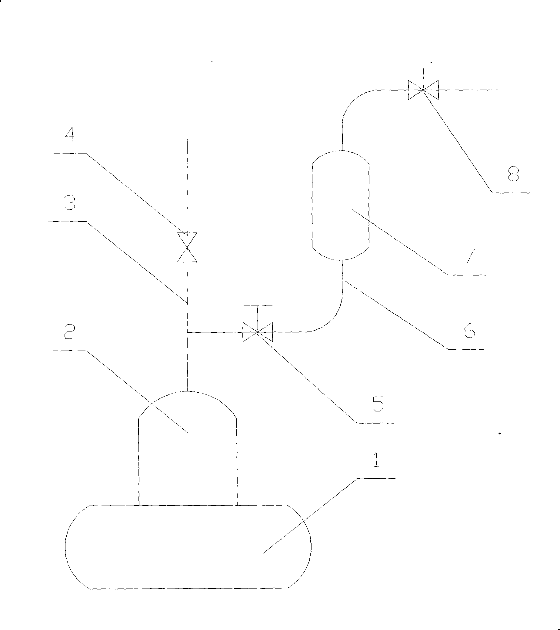
[0008] The main functions of the present invention are firstly to reduce the discharge of steam as much as possible while ensuring the effective discharge of oxygen, and secondly to form a stable pressure in the deaeration tower to increase the temperature in the deaeration tower and strengthen the deoxygenation effect.

[0009] Therefore, when implementing the method of the present invention, in addition to avoiding exceeding the maximum design pressure of the equipment for the control of the exhaust of the gas storage tank based on the pressure requirements in the deoxidation tower, it is also necessary to ensure a certain non-discharge time. The overall space formed by the gas storage tank forms a relatively stable layered distribution state of water, steam and gas, so that all or most of the space in the gas storage tank is dominated by gases such as oxygen, and the connecting pipe is closed when exhausting The connecting valve on the top, the material discharged outside is...


PUM


Abstract

The invention relates to an energy-saving method of thermal deaerating and a transformed device of a thermal deaerator, wherein the top of the thermal deaerator body is connected to a deaerating buffer tank, or called a gas holder, by a connecting pipe; the top of the gas holder is equipped with an exhaust pipe; the deaerator body comprises a deaerating tower and a water tank which is mounted at the bottom of the deaerator body, adopts the mode of steam heating to achieve continuous deaerating, while the gas holder adopts the mode of intermittent exhaust to exhaust gases, otherwise, a connecting valve on the connecting pipe is opened, and an exhaust valve on the exhaust pipe is closed; the matter distribution mode that the lower part is hot water, the middle is predominated by steam and the upper part is predominated by oxygen and other gases is formed inside the integral space comprising the water tank, the deaerating tower and the gas holder; and the valve is controlled to exhaust when part of the space inside the gas holder is predominated by oxygen and other gases. The method and the transformed device are conducive to saving water resources and heat energy, and essentially can be used in the transformation of thermal deaerating of boiler feed water.

Description

technical field [0001] The invention relates to a thermal deoxygenation and energy-saving method, and also relates to an energy-saving thermal deaerator adopting the method, which can be mainly used for thermal deoxidation of boiler feed water. Background technique [0002] China No. 200420120557.0 utility model patent application discloses a low-level thermal deaerator, which includes a deaerator body and a water pump. The deaerator body is mainly composed of a deaeration tower and a water tank. There are steam inlet pipe, water inlet pipe and steam exhaust pipe. The water pump is located under the deaerator body and connected with the water tank. The steam exhaust pipe is provided with an automatic control valve. This deaerator eliminates a series of defects such as large civil construction investment, difficult hoisting, long construction period, and certain cavitation to the water pump of common high-level thermal deaerators, and by setting an automatic control valve on ...

Claims


Application Information

Patent Timeline
Patent Type & Authority Applications(China)
IPC IPC(8): C02F1/20
Inventor 李树生
Owner 李树生
Why Eureka
Try Eureka