Cooling system of engine for small-sized vehicle

A technology for a cooling system and an engine, which is applied to the cooling of the engine, engine components, machines/engines, etc., can solve the problems of increasing the number and complicated layout of radiator ducts, and achieves an increase in the freedom of layout, simplification of duct layout, and the number of parts. reduced effect

Inactive Publication Date: 2009-01-14
HONDA MOTOR CO LTD
View PDF1 Cites 9 Cited by
  • Summary
  • Abstract
  • Description
  • Claims
  • Application Information

AI Technical Summary

Problems solved by technology

Therefore, the number of parts increases and the duct layout around the radiator is complicated

Method used


Image

  • Cooling system of engine for small-sized vehicle
  • Cooling system of engine for small-sized vehicle
  • Cooling system of engine for small-sized vehicle

Examples


Embodiment Construction

[0036] Embodiments of the present invention shown in the drawings will be described below.

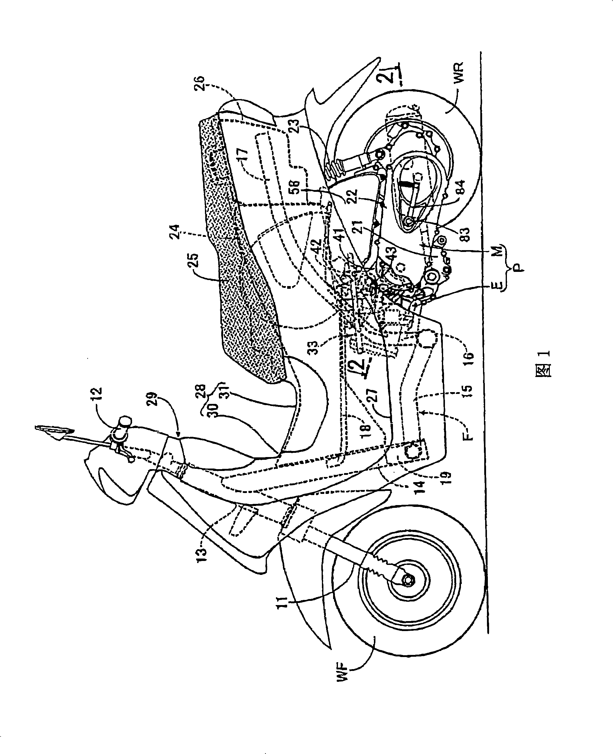
[0037] First, as shown in FIG. 1, the main body frame F of a scooter-type motorcycle as a small vehicle is equipped with a head pipe 13 that operably supports a front fork 11 and an operating handle 12, and the front fork 11 is mounted on the front fork. Its lower end supports the front wheel WF with a shaft and straddles the front wheel WF, and the operating handle 12 is connected to the upper end of the front fork 11; a cylindrical main pipe 14, which extends backward and downward from the head pipe 13; a pair of left and right A lower frame 15, which is connected to the lower portion of the main pipe 14 and extends rearward; a cross pipe 16, which connects the rear ends of the two lower frames 15; a pair of left and right rear frame pipes 17, each front end of which is connected to the cross pipe 16 at both ends; and an upper frame 18 each connecting the middle portion of the main p...


PUM


Abstract

In order to reduce the number of parts, to enable air to bleed from a water jacket and to simplify a conduit layout around a radiator in a cooling system of an engine for a small-sized vehicle, an engine main unit is rockably supported by a body frame via a supporting shaft and the radiator at least a part of which is arranged on the downside of the supporting shaft in a side view is supported by a crankcase on the side of the crankcase. A radiator 96 is arranged on the side of a crankcase with a front end arranged in front of a supporting shaft; from a side view, a leading-out pipe 140 provided to an engine main unit 33 for leading cooling water from an uppermost part of a water jacket of the engine main unit 33 and an inlet pipe 139 provided to an upper tank 100 of the radiator 96 on the upside of the supporting shaft 43 are coupled via a conduit 141 passing the upside of the supporting shaft 43 in a side view to be higher from the leading-out pipe 140 to the side of the inlet pipe 139.

Description

technical field [0001] The present invention relates to a cooling system of an engine for a small vehicle, wherein an engine main unit provided with a water jacket is swingably supported by a main body frame via a support shaft, and heat is radiated on the side of the crankcase forming a part of the engine main unit. The radiator is supported by a crankcase in which an upper case and a lower case in a radiator are coupled with a cooling core, and at least a part of the radiator is arranged on a lower side of a support shaft in a side view. Background technique [0002] Patent document JP03-696508A, hereinafter referred to as patent document 1, is known in which, in a side view, a support shaft for supporting an engine main unit by a main body frame is located on the upper side in front of the radiator, and the radiator is arranged on the engine side. Crankcase side of the main unit. [0003] In the invention disclosed in Patent Document 1, the uppermost portion of the radia...

Claims


Application Information

Patent Timeline
Patent Type & Authority Applications(China)
IPC IPC(8): F01P3/18F01P11/10B62J39/00
Inventor 平山周二山西辉英
Owner HONDA MOTOR CO LTD
Why Eureka
Try Eureka