
Length measuring device

A technology of length measurement and measurement direction, which is applied in the field of length measurement devices, can solve problems such as inaccurate measurement and scale length changes, and achieve high measurement accuracy and compact structure.

Active Publication Date: 2009-01-14
DR JOHANNES HEIDENHAIN GMBH
View PDF3 Cites 6 Cited by
  • Summary
  • Abstract
  • Description
  • Claims
  • Application Information

AI Technical Summary

Problems solved by technology

This heating causes a change in the length of the scale and leads to inaccurate measurements

Method used


Image

  • Length measuring device
  • Length measuring device
  • Length measuring device

Examples


Embodiment Construction

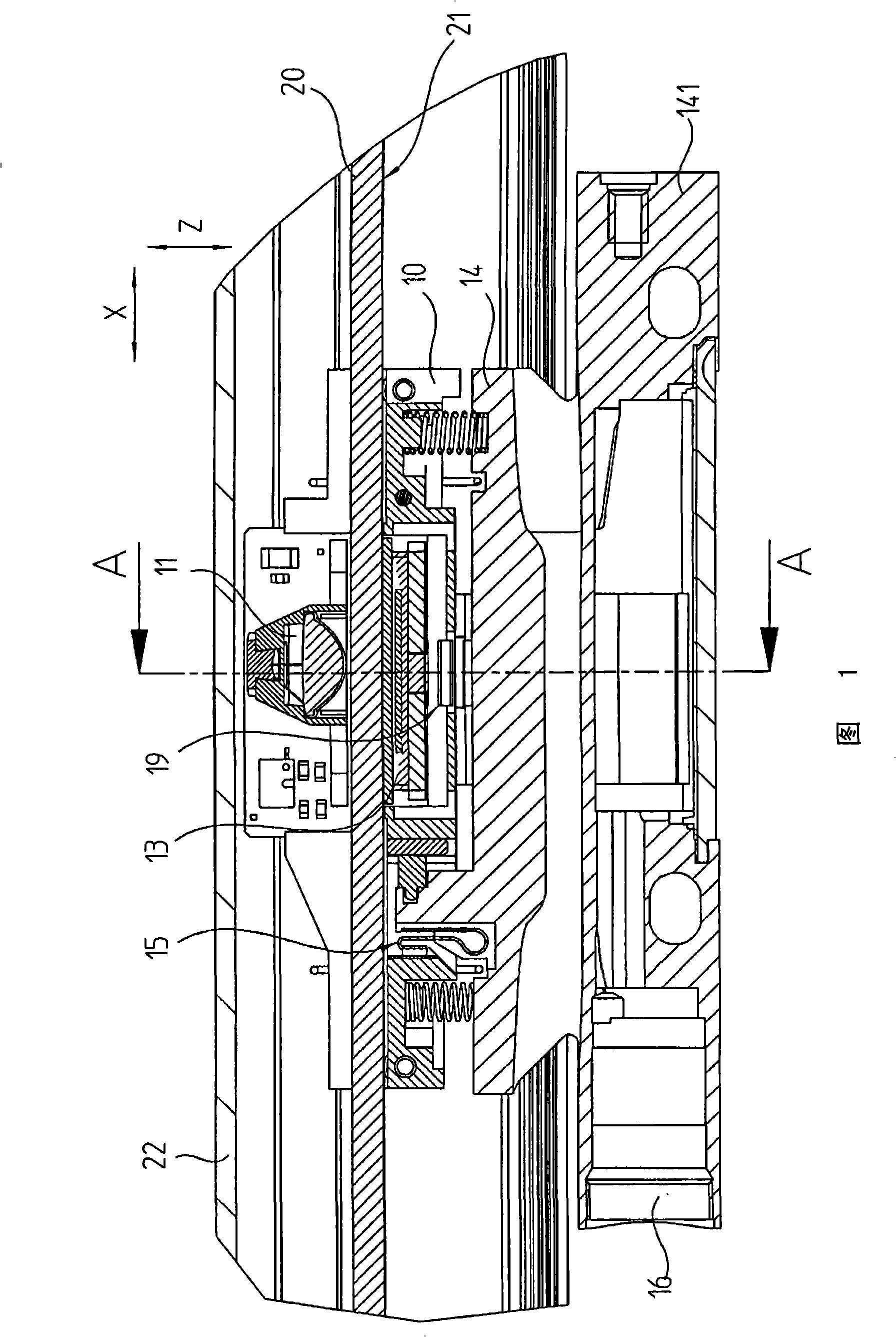
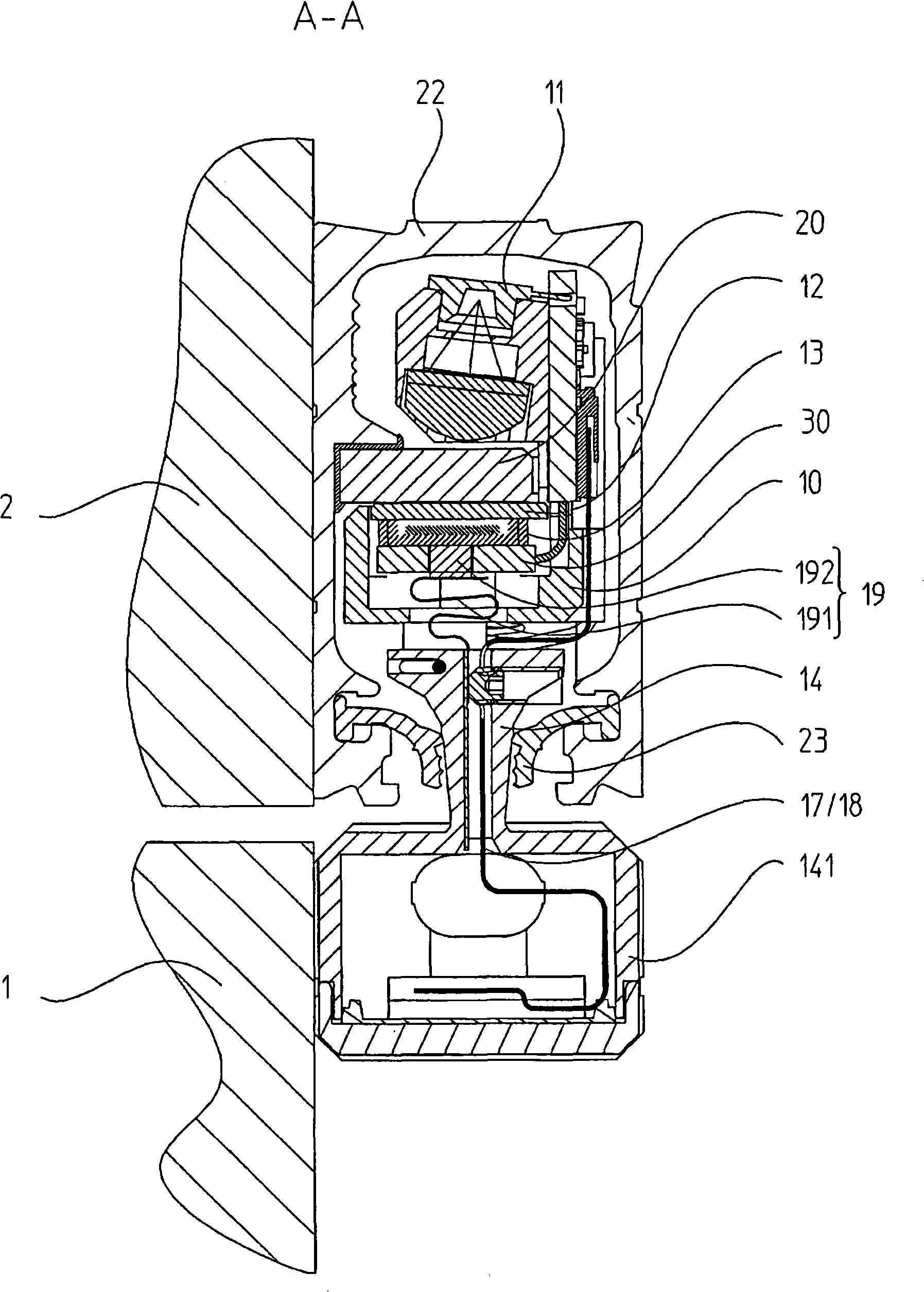
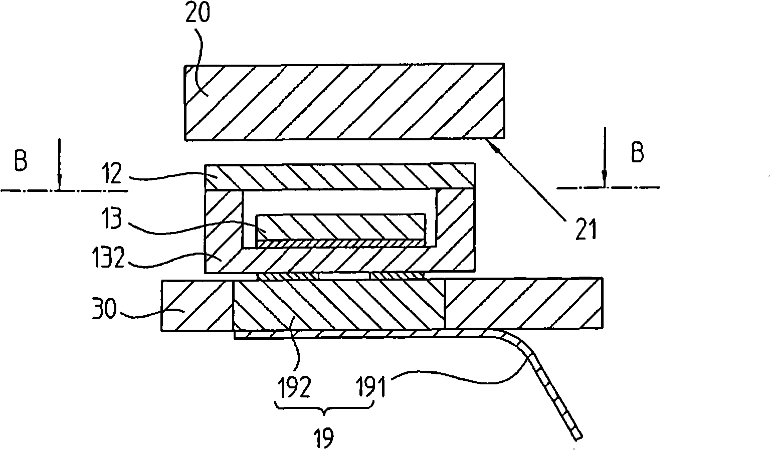
[0019] The invention will be described using an optical length measuring device as an example. The relative position of two objects 1 and 2 that are movable relative to each other in the measuring direction X is measured with this length measuring device. In this case, the transparent scale 20 is scanned by a scanning unit 10 which is movable in the measuring direction X relative to the scale 20 . The scale 20 has a measuring division 21 . The scanning unit 10 scans the measuring scale with transmitted light. For this purpose, the scanning unit 10 has an illumination unit 11 . The lighting unit emits a light beam. This light beam is directed through the scale 20 and further through the transparent scanning plate 12 and finally strikes the light-sensitive scanning sensor 133 of the sensor chip 13 . In this case, the light beam is modulated in relation to the position of the measuring graduation 21 on the scale 20 .

[0020] The scale 20 is provided inside the housing 22 . ...


PUM


Abstract

A length-measuring device is composed of a scale (20) having a housing, a sensor chip (13) of a scanning unit (10) for scanning the scale (20). A follower (14) rigidly and transversely coupled on the scanning unit (10) movably along a measurement direction X through a coupling mechanism (15). Heat generated by the sensor chip (13) is transmitted from the scale (20) to the follower (14) with pertinence. Therefore, a heat conducting element (19) is coupled on the sensor chip (13), wherein the heat conducting element is led to the follower (14) and is configured to be flexible, to compensate movement allowed by the coupling mechanism (15).

Description

technical field [0001] The invention relates to a length measuring device according to the preamble of claim 1 . Background technique [0002] Such a type of length measuring machine is described, for example, in DE 29 29 989 A for measuring lengths as well as strokes, and in particular in machining machines for measuring the relative movement of a tool relative to a workpiece to be machined, and in coordinate measuring Machines are used, and are also increasingly used in the semiconductor industry. [0003] In this case a scale is used as the scale. In order to prevent the influence of the external environment, the scale is arranged in the casing. A change in temperature inside the housing will cause a change in the length of the scale depending on the scale material. These length variations cause measurement errors. [0004] In order to keep this temperature change as low as possible, it is proposed according to DE 101 64 404 A1 to temperature-condition the interior of...

Claims


Application Information

Patent Timeline
Patent Type & Authority Applications(China)
IPC IPC(8): G01B11/02G12B15/06
CPCG01D5/264
Inventor A·阿法J·豪恩赖特
Owner DR JOHANNES HEIDENHAIN GMBH
Learn More