Method for detecting period transient state characteristic in signal

A detection method and signal technology, applied to vibration measurement in solids, measuring vibration, measuring devices, etc., can solve the problems of tediousness, low efficiency and accuracy, improve efficiency and accuracy, realize automatic identification, and realize fault detection Effect

Inactive Publication Date: 2009-01-14
SUZHOU UNIV
View PDF0 Cites 13 Cited by
  • Summary
  • Abstract
  • Description
  • Claims
  • Application Information

AI Technical Summary

Problems solved by technology

However, for periodic transient features, it is necessary to read the period on the time-frequency diagram, which is cumb

Method used


Image

  • Method for detecting period transient state characteristic in signal
  • Method for detecting period transient state characteristic in signal
  • Method for detecting period transient state characteristic in signal

Examples


Embodiment 1

[0041] Embodiment 1: Detection of a local fault of a bearing

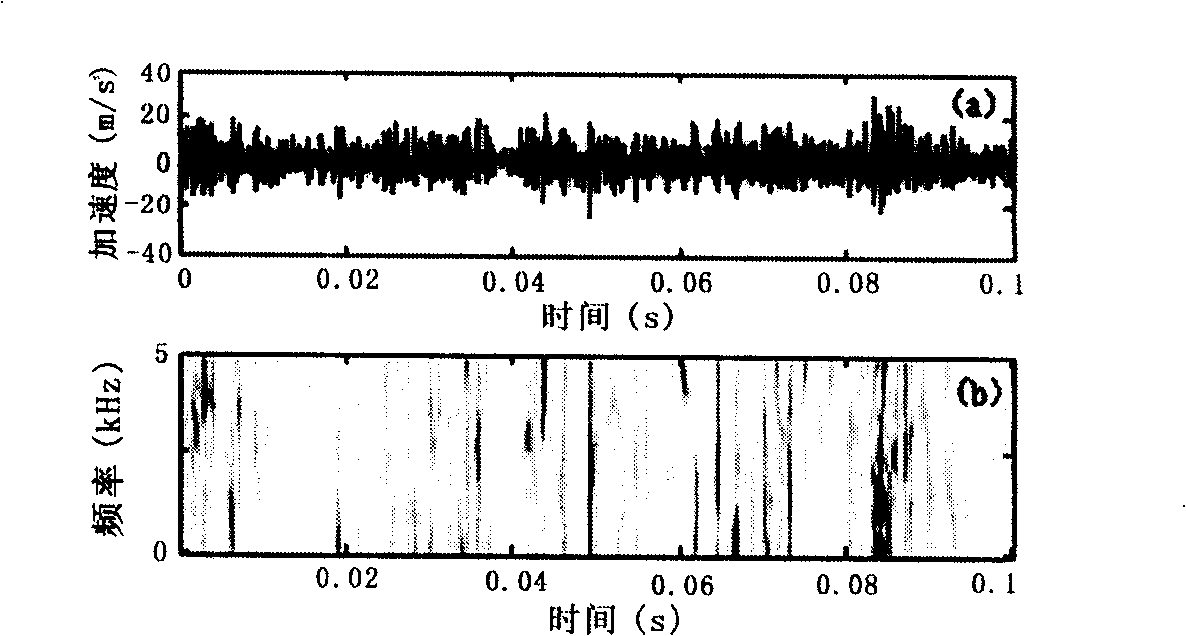
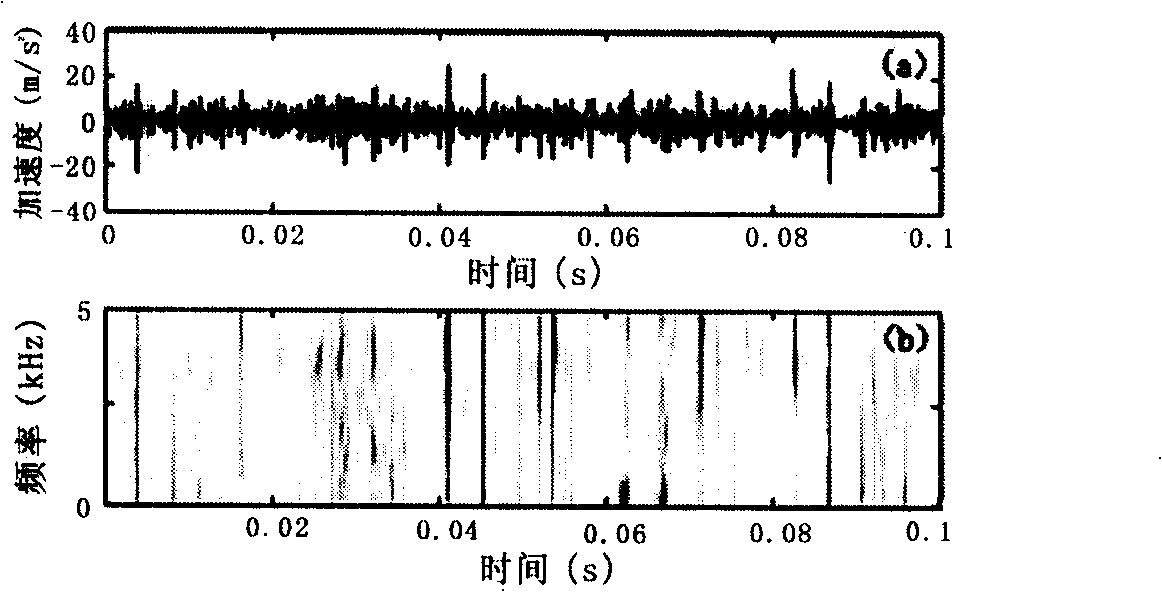
[0042] The outer ring, inner ring and rolling elements of the bearing are the main parts of bearing faults. Local faults (such as local spalling, corrosion, etc.) in these parts often cause transient shocks in bearing vibration. In this case, there are periodic transient shocks in the vibration signal. However, due to the short duration of the vibration caused by local faults, and the transient impact is often mixed in the background noise, the performance is not obvious. detection.

[0043] The experimental object is the tapered roller bearing installed on the shaft end of the reducer, the model is 33207. During the test, the piezoelectric acceleration sensor is installed on the reducer housing close to the bearing. The vibration acceleration signal is collected and stored by the computer after passing through the piezoelectric acceleration sensor and the charge amplifier.

[0044]The test is carried out under...

Embodiment 2

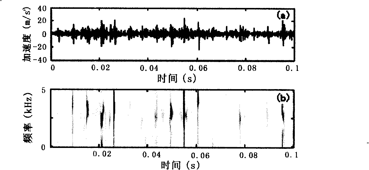
[0057] Embodiment 2: Gear Broken Teeth Fault Detection

[0058] When a tooth of the gear is broken, there will be a transient impact component in the vibration signal, and this component will be loaded in the noise and the meshing frequency of the gear, and it needs to be detected to express it with clear features.

[0059] The object is the fault detection of the third-gear meshing gear of an automobile transmission. The power transmission structure of the gearbox is as follows: Figure 9 shown. During the test, a piezoelectric acceleration sensor is installed on the casing of the transmission to pick up vibration acceleration signals. The vibration acceleration signal is collected and stored by the computer after passing through the piezoelectric acceleration sensor and the charge amplifier.

[0060] For the third gear of the gearbox, there are four periods: the rotation period of the driving gear, the rotation period of the driven gear, the rotation period of the constant...


PUM


Abstract

The invention discloses a test method of periodic transient characteristics in signals, uses a sensing device for inputting and implementing analog-to-digital conversion, obtains a signal x(t), and detects whether the transient characteristics with a period T1, T2 or Tm exist in the signal x(t), where m is a positive integer. The test method is characterized in that the test method comprises the following steps: the time frequency decomposition of the signal x(t) is implemented, and the time frequency representation TFRX(t, f) of the signal characteristics is obtained; m polar coordinate mappings are respectively built according to the periods T1, T2 or Tm; each mapping is represented on a polar coordinate figure; when enhanced characteristic representation appears in the polar coordinate figure that is corresponding to the period Tn (n lies in a closed interval between 1 and m), whether the transient characteristics with the period Tn exist in the detected signal is decided. The test method of the periodic transient characteristics in signals conveniently realizes period deciding, improves the efficiency and the accuracy of period deciding, can realize automatic detection of the periodic transient characteristics, and is particularly applicable to automatic failure identification of mechanical equipment.

Description

technical field [0001] The invention relates to a method for analyzing and detecting signals, in particular to a method for detecting periodic transient characteristics in signals, which can be used for fault diagnosis and state monitoring of mechanical equipment and detection of biomedical signals. Background technique [0002] The detection of transient components in signals, especially the detection of periodic transient features, has a wide range of applications in the fields of fault diagnosis and status monitoring of mechanical equipment, and detection of biomedical signals. Because there are noises caused by various reasons in the signal obtained during the detection process, the transient components will also be polluted by noise. [0003] The most direct transient component detection method is to directly judge whether there is a transient component in the time domain signal, but because the transient component in the signal is often mixed in the noise, the accuracy...

Claims


Application Information

Patent Timeline
IPC IPC(8): G01H1/00G01M13/04G01M13/02
Inventor 朱忠奎伍小燕张茂青罗力恒
Owner SUZHOU UNIV
Why Eureka
Try Eureka