
Capacitive electromagnetic potential transformer used in power system

A voltage transformer and power system technology, applied in the direction of inductors, transformers, transformer/inductor coils/windings/connections, etc., can solve problems such as poor stability, high accuracy affected by temperature, poor transient response characteristics, etc., to achieve Prevent ferromagnetic resonance, simple structure, good transient response characteristics

Inactive Publication Date: 2009-01-14
张安斌 +1
View PDF0 Cites 2 Cited by
  • Summary
  • Abstract
  • Description
  • Claims
  • Application Information

AI Technical Summary

Problems solved by technology

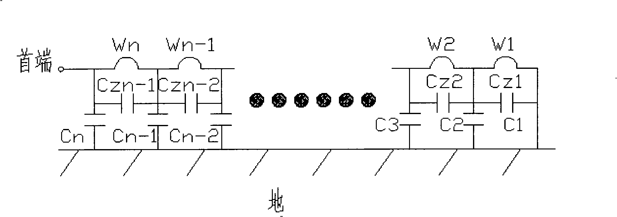
After the voltage transformer resonates, the non-power frequency energy or "excited" energy generated by its own saturation makes the voltage transformer deeply saturated, so it is difficult for the voltage transformer to disappear after saturation
The current solutions mainly include: choose a voltage transformer with better excitation characteristics, add a linear resistor to the open triangle winding of the voltage transformer, install an automatic microcomputer harmonic elimination device on the open triangle of the voltage transformer, and connect the primary neutral point of the voltage transformer to zero sequence. The voltage transformer, the LXQ resonance eliminator connected between the primary neutral point of the voltage transformer and the ground, etc. have their own advantages, but also have their own disadvantages, and they cannot fully solve the problem of ferromagnetic resonance of the voltage transformer.
[0006] In order to prevent ferromagnetic resonance at voltage levels above 110kV, CVT capacitive voltage transformers are used, but the transient response characteristics are worse than electromagnetic ones, the structure is complex, the volume is large, the manufacturing price is high, the stability is poor, and the accuracy is greatly affected by temperature.

Method used


Image

  • Capacitive electromagnetic potential transformer used in power system
  • Capacitive electromagnetic potential transformer used in power system
  • Capacitive electromagnetic potential transformer used in power system

Examples


Embodiment 1

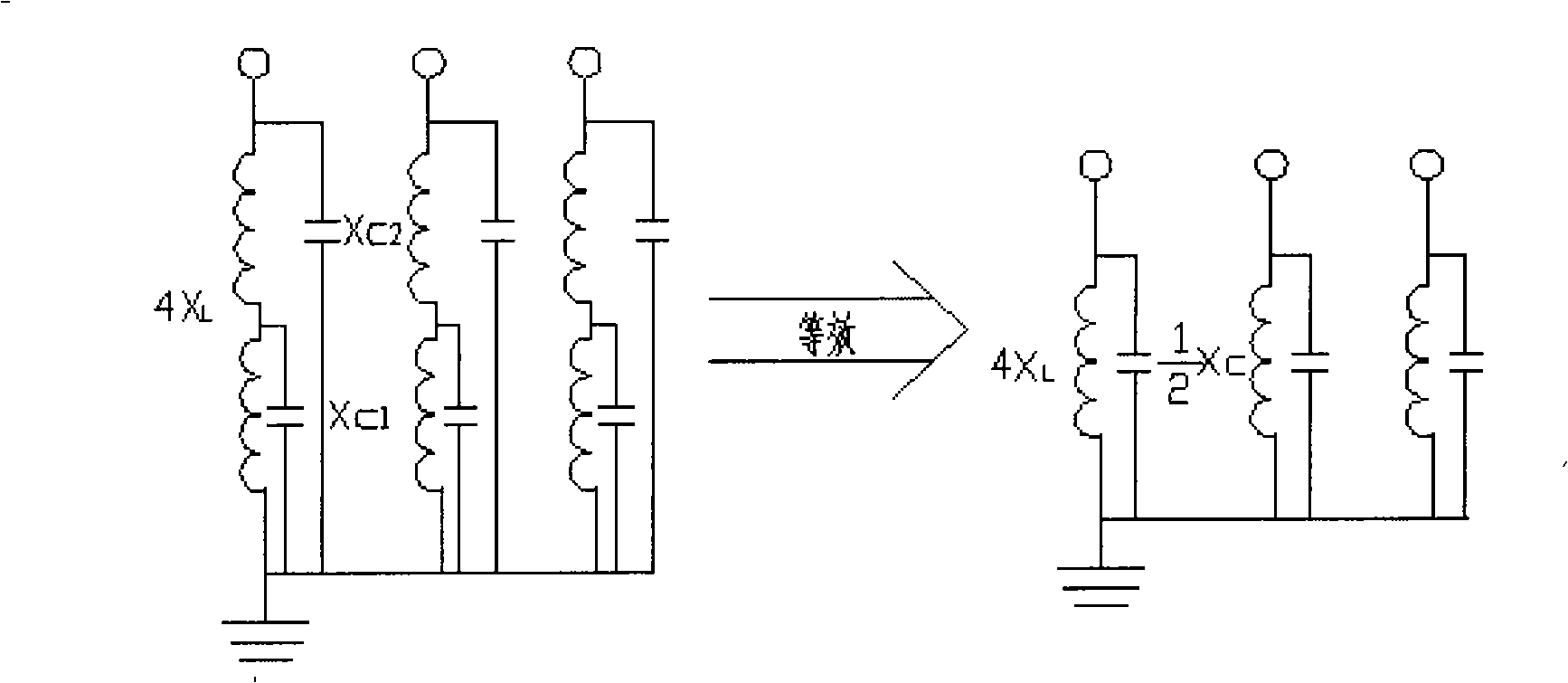
[0021] see figure 2 , for the number of turns of the primary side winding is n1, and the inductance is X L , The equivalent capacitive reactance to ground is X C , and X C L Inductive voltage transformer, in this embodiment, set the number of turns of the primary side winding of the voltage transformer to be 2n1, then the inductive reactance of the voltage transformer increases by about 4X L , the equivalent capacitive reactance to ground is reduced by about X C / 2, obviously, the capacitive reactance to ground is reduced by 8 times relative to the inductive reactance, because it satisfies: X C / 2L , therefore, the voltage transformer is capacitive.

Embodiment 2

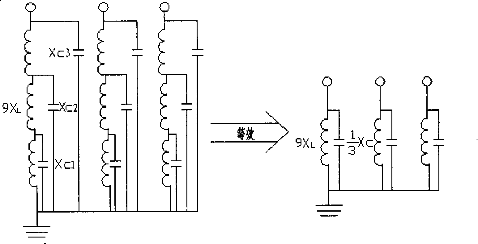
[0023] see image 3 , for the number of turns of the primary side winding is n1, and the inductance is X L , The equivalent capacitive reactance to ground is X C , and X C L In this embodiment, if the number of turns of the primary side winding of the voltage transformer is set to 3n1, the inductive reactance of the voltage transformer increases by about 9X L , the equivalent capacitive reactance to ground is reduced by about X C / 3, obviously, the capacitive reactance to ground is reduced by 27 times relative to the inductive reactance, because it satisfies: X C / 3L , therefore, the voltage transformer is capacitive.

[0024] The electromagnetic voltage transformer of the present invention can be widely used in power systems above 3kV. It is the same as the prior art. Its specific application is to set up independent voltage transformers corresponding to each phase, and the primary side and one end of each voltage transformer are connected to the phase. The other end is ...


PUM


Abstract

The invention provides a capacitive electromagnetic voltage transformer which is applied to a power system and characterized in that the primary side winding turns are arranged so as to lead the grounding equivalent capacitance 1 / Omega C of the primary side winding of the voltage transformer is less than the primary side winding inductance Omega L; the primary side resistance of the transformer presents capacitive. By reasonably arranging the primary winding turns, the capacitive electromagnetic voltage transformer leads the voltage transformer to present capacitive; the capacitive voltage transformer and a system capacitor can not form an LC circuit, thus effectively preventing the generation of ferromagnetic resonance of the voltage transformer; meanwhile, advantages of the electromagnetic voltage transformer such as simple structure, good transient response characteristic and being not affected by environmental temperature are sufficiently exerted.

Description

technical field [0001] The invention relates to the application of voltage transformers for power transmission and distribution, power plants and substations in power systems. Background technique [0002] Electromagnetic voltage transformers are widely used in power systems. Ferromagnetic resonance occurs in systems above 110kV, so CVT capacitor voltage transformers are used in 110kV systems. Corresponding to each phase, separate independent voltage transformers are set up. One end of the primary side of each voltage transformer is connected to the phase line, and the other end is grounded. The voltage is output on the secondary side of the voltage transformer for use by instruments and related protection controls. . [0003] Under the normal working voltage of the electromagnetic voltage transformer in the prior art, the magnetic density of the iron core is usually not high, the iron core is not saturated, the equivalent capacitive reactance to the ground is greater than ...

Claims


Application Information

Patent Timeline
Patent Type & Authority Applications(China)
IPC IPC(8): H01F38/24H02H7/05H01F27/28
Inventor 张安斌王学才
Owner 张安斌
Learn More