
Processing system for large moisture rouging, degreasing, recycling oil and water, and reusing the same

A treatment system and water recovery technology, applied in the field of treatment systems, can solve the problems of inability to solve oil-water emulsification, small separation effect processing capacity, and high water content in the extracted oil, and achieve the effects of avoiding oil-water emulsification, simple equipment and simple operation.

Inactive Publication Date: 2009-01-21
陈太宏
View PDF0 Cites 0 Cited by
  • Summary
  • Abstract
  • Description
  • Claims
  • Application Information

AI Technical Summary

Problems solved by technology

[0002] At present, there are three known oil-water separation technologies: (1) It adopts gravity static separation, which utilizes the characteristics of oil-water specific gravity difference to let the oil float up, and then scrape it out with an oil scraper for recycling, or use a floating ball suction head Suck out the slick oil, but there is still a lot of water in the taken out oil, and the problem of oil-water emulsification cannot be solved
(2) It is a chemical treatment method, which mainly uses acid to crack and separate the oil and float it out, but the acidic water must be added to the alkali, which is inconvenient to use and will produce sludge; (3) Centrifugal separation method: use high-speed The difference of the separation center is generated during the rotation, and the oil and water with different specific gravity can be separated, but the processing capacity of the separation effect is small, and the equipment price is high

Method used


Image

  • Processing system for large moisture rouging, degreasing, recycling oil and water, and reusing the same
  • Processing system for large moisture rouging, degreasing, recycling oil and water, and reusing the same

Examples


Embodiment Construction

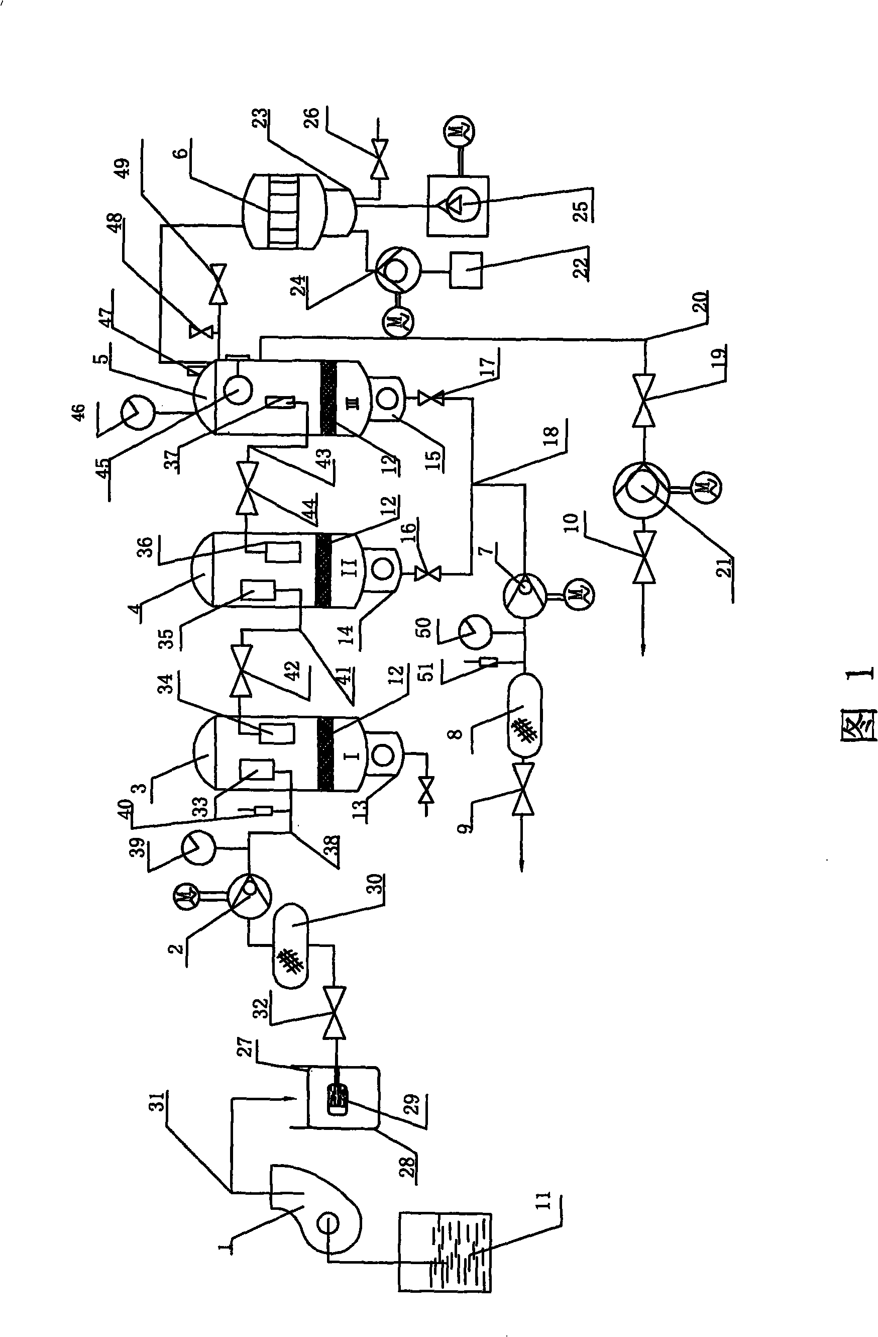
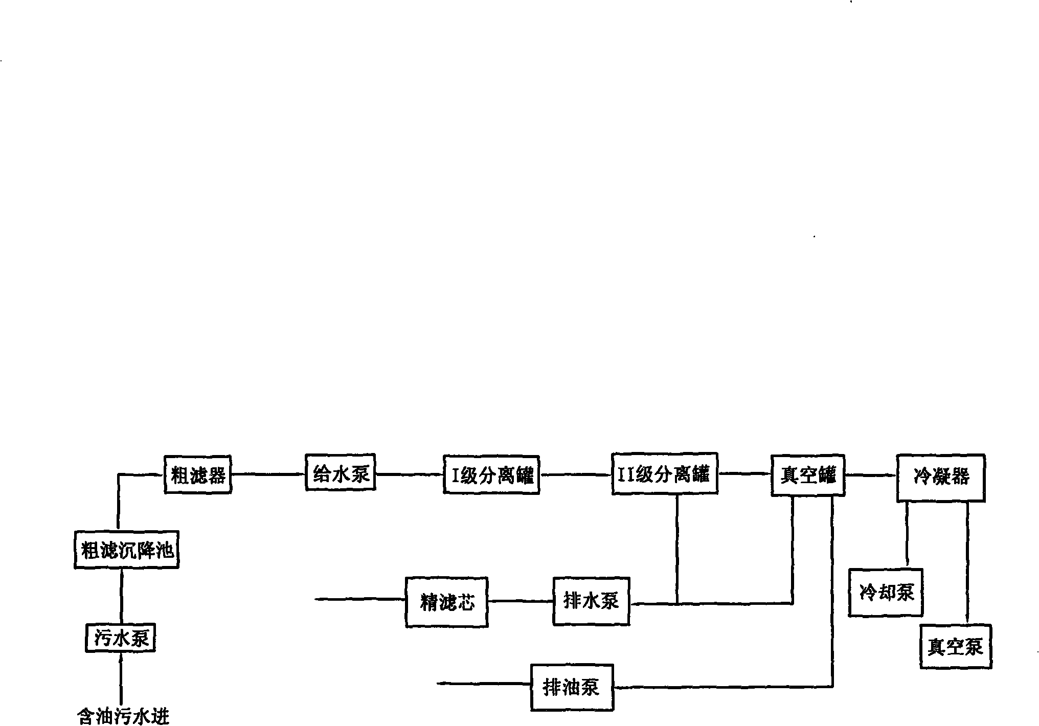
[0010] In Fig. 1, the present invention provides a treatment system for removing impurities from large amounts of water, removing oil and reusing oil and water, which includes a sewage pump 1, a pre-stage coarse filter device, a feed water pump 2, and a first-stage separation tank 3 , Class II separation tank 4, vacuum tank 5, condenser 6, drain pump 7, fine filter 8, water outlet check valve I9, oil drain pump 21, oil drain check valve 10 and oil drain ball valve 19, input of sewage pump 1 end into the sewage pool 11, the sewage pump 1 is connected with the pre-stage coarse filter device, feed water pump 2, I-level separation tank 3, II-level separation tank 4, vacuum tank 5, and condenser 6 in turn, and the I-level separation tank 3 , II-level separation tank 4, vacuum tank 5 are respectively provided with isolation filter screen 12, isolation filter screen 12 is positioned at the lower part of I-level separation tank 3, II-level separation tank 4, vacuum tank 5, and I-level ...


PUM


Abstract

The invention relates to a processing system which can remove impurities and oil from materials with high water content and recycle oil and water for reusing. A sewage pump of the processing system is sequentially connected with a forestage rough filtration device, a water-feeding pump (2), a I stage separating tank (3), a II stage separating tank (4), a vacuum tank (5) and a condenser (6), isolating strainers (12) are respectively arranged in the I stage separating tank (3), the II stage separating tank (4) and the vacuum tank (5) and positioned at the lower half parts of the I stage separating tank (3), the II stage separating tank (4) and the vacuum tank (5), the outlets of a water storage barrel II (14) and a water storage barrel III (15), which are respectively arranged at the bottoms of the II stage separating tank (4) and the vacuum tank (5), pass through a water drain ball valve (16) and a water drain check valve II (17) respectively and then are merged into a transmission pipeline (18) which is connected with a draining pump (7), a fine strainer (8) and an effluent check valve I (9), and the side of the vacuum tank (5) is connected with an oil draining check valve (10).

Description

technical field [0001] The invention relates to a treatment system for removing impurities and oil from large amounts of water to recycle oil and water for reuse. Background technique [0002] At present, there are three known oil-water separation technologies: (1) It adopts gravity static separation, which utilizes the characteristics of oil-water specific gravity difference to let the oil float up, and then scrape it out with an oil scraper for recycling, or use a floating ball suction head Suck out the slick oil, but there is still a lot of water in the taken out oil, and the problem of oil-water emulsification cannot be solved. (2) It is a chemical treatment method, which mainly uses acid to crack and separate the oil and float it out, but the acidic water must be added to the alkali, which is inconvenient to use and will produce sludge; (3) Centrifugal separation method: use high-speed The difference of the separation center is generated during the rotation, and the oi...

Claims


Application Information

Patent Timeline
Patent Type & Authority Applications(China)
IPC IPC(8): B01D17/02C02F1/40
Inventor 陈太宏
Owner 陈太宏
Learn More