
Vertical type ceramic injection machine

An injection machine and ceramic technology, applied in the field of injection machines, can solve the problems of uneven mixing, uneven temperature, poor effect, etc., and achieve the effect of good product quality, enhanced effect and good quality.

Inactive Publication Date: 2009-01-21
东莞市天合电子陶瓷制品有限公司
View PDF0 Cites 5 Cited by
  • Summary
  • Abstract
  • Description
  • Claims
  • Application Information

AI Technical Summary

Problems solved by technology

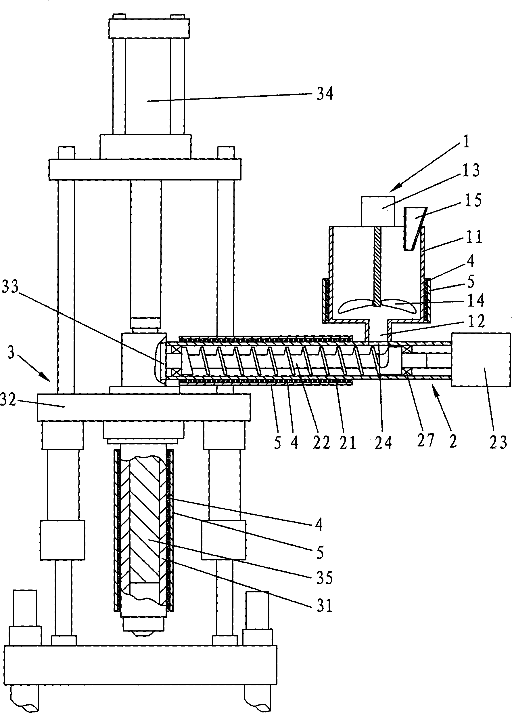
[0003] At present, the ceramic injection molding process generally processes the ceramic material into a slurry, then injects it into the mold with an injection machine, and forms it after cooling. The injection machine used in the ceramic injection molding process is generally an injection machine for injecting plastics. This injection machine includes a feeding device, an injection device, etc. The feeding device is a hopper, the top of the hopper is open, and the bottom is provided with a discharge port. Since this injection machine is mainly used for injecting plastics, it is added to the feeding device. The raw material is solid particles, and the ceramic material added to the feeding device in the ceramic injection molding process is slurry. The effect of ceramic injection molding using an injection machine for plastic injection is not good, and the slurry-like ceramic material will appear in the feeding hopper. Inhomogeneous mixing and uneven temperature. At the same time, the feeding device is directly connected to the injection device. During the process of feeding the slurry from the feeding device to the injection device, the feeding amount and flow rate are difficult to control, which affects the quality of the injection molded product. And the slurry is prone to coagulation due to low temperature

Method used


Image

  • Vertical type ceramic injection machine

Examples


Embodiment Construction

[0018] Below in conjunction with accompanying drawing, the present invention will be further described, see figure 1 , a vertical ceramic injection machine, which includes a feeding device 1 and an injection device 3, wherein the feeding device 1 includes a barrel 11, the top of the barrel 11 is open, and the bottom is provided with a discharge port 12, and the feeding device 1 and the injection The device 3 is connected by a feeding device 2, and a stirring device is provided inside the material barrel 11. The stirring device includes a motor 13 and a stirring blade 14, the motor 13 is fixed on the top of the material barrel 11, and the stirring blade 14 is connected to the output end of the motor 13 and extends Into the bottom of the material barrel 11, and the top of the material barrel 11 is provided with a hopper 15 for adding slurry. Since the feeding device 1 is provided with a stirring device to stir the slurry, the mixing and temperature of the slurry are relatively u...


PUM


Abstract

The invention relates to the technical filed of injection machines, in particular to a vertical ceramic injection machine. The injection machine comprises a feeding device and a jet device; wherein, the feeding device comprises a charging basket; the top of the charging basket is provided with an opening, and the bottom is opened with a discharge hole. The feeding device is connected with the jet device by a conveying device. The interior of the charging basket is provided with a stirring device. The conveying device comprises a feeding barrel, a feeding screw, and a servo Motor. The feeding barrel is provided with a delivery opening communicated with the discharge hole of the charging basket. After being stirred by the stirring device, the slurry stirred by the stirring device enters the feeding barrel from the delivery opening of the feeding barrel. The feeding screw is rotated due to being driven by the servo motor and pushes the slurry to the jet device from the feeding barrel. The feeding quantity and flow speed of the slurry delivered into the jet device can be controlled by adjusting the rotational speed and the rotational time of the servo motor. After injection molding, products have good quality, therefore, the conveying device additionally arranged for vertical ceramic injection machine increases the injection molding effect of the ceramic slurry.

Description

Technical field: [0001] The invention relates to the technical field of injection machines, in particular to a vertical ceramic injection machine. Background technique: [0002] The performance of ceramic materials depends on its composition and structure, and the composition and structure depend on the formulation and preparation process, so the performance of materials is closely related to the process. Molding technology is one of the three key technologies for preparing high-performance ceramic parts. High-performance ceramic parts must be realized through suitable molding processes and injection machines, and ceramic colloidal molding technology is currently the main method for molding ceramics. As a key link in the preparation process of high-performance ceramics, the molding process of ceramics affects the reliability and manufacturing cost of ceramic materials. [0003] At present, the ceramic injection molding process generally processes the ceramic material into a...

Claims


Application Information

Patent Timeline
IPC IPC(8): B28B3/22B28C1/02
Inventor 黄沛恩吕小军
Owner 东莞市天合电子陶瓷制品有限公司
Learn More