Single-phase miniature electric bicycle

A single-phase, miniature technology, applied in the direction of traveling mechanism, load suspension components, transportation and packaging, etc., can solve the problems of no braking function, inconvenient installation and use, and increased production costs

Active Publication Date: 2009-01-21
BADA MECHANICAL & ELECTRICAL
View PDF0 Cites 1 Cited by
  • Summary
  • Abstract
  • Description
  • Claims
  • Application Information

AI Technical Summary

Problems solved by technology

The structure of the existing electric vehicle is generally provided with two rows of rollers on the left and right, one row of rollers is driven by a motor, and the other row of rollers is a passive wheel, and the driving wheel and the driven wheel are respectively installed on the driving wheel mounting plate and the passive wheel. On the board, the two mounting plates are fixedly connected by connecting shafts. The driving wheel and the driven wheel frame are rollingly matched with the guide rail on the guide rail. The guide rail is generally made of I-shaped steel. Rolling along the side surface, the driving wheel mounting plate of the electric trolley is equipped with a motor reducer in addition to the driving wheel. When the electric trolley is unloaded, due to the unbalanced quality on both sides of the guide rail, it will appear unstable. It is not safe to use, and the motor reducer is driven by an ordinary single-phase asynchronous motor without a braking function, resulting in a great potential safety hazard in the operation of the electric vehicle
The existing solution to the problem of mass imbalance is to add a balance iron block on the side of the passive wheel mounting plate to balance the weight of the motor reducer. Obviously, adding iron blocks increases the production cost of the product, and it is not convenient to install and use.

Method used


Image

  • Single-phase miniature electric bicycle
  • Single-phase miniature electric bicycle

Examples


Embodiment Construction

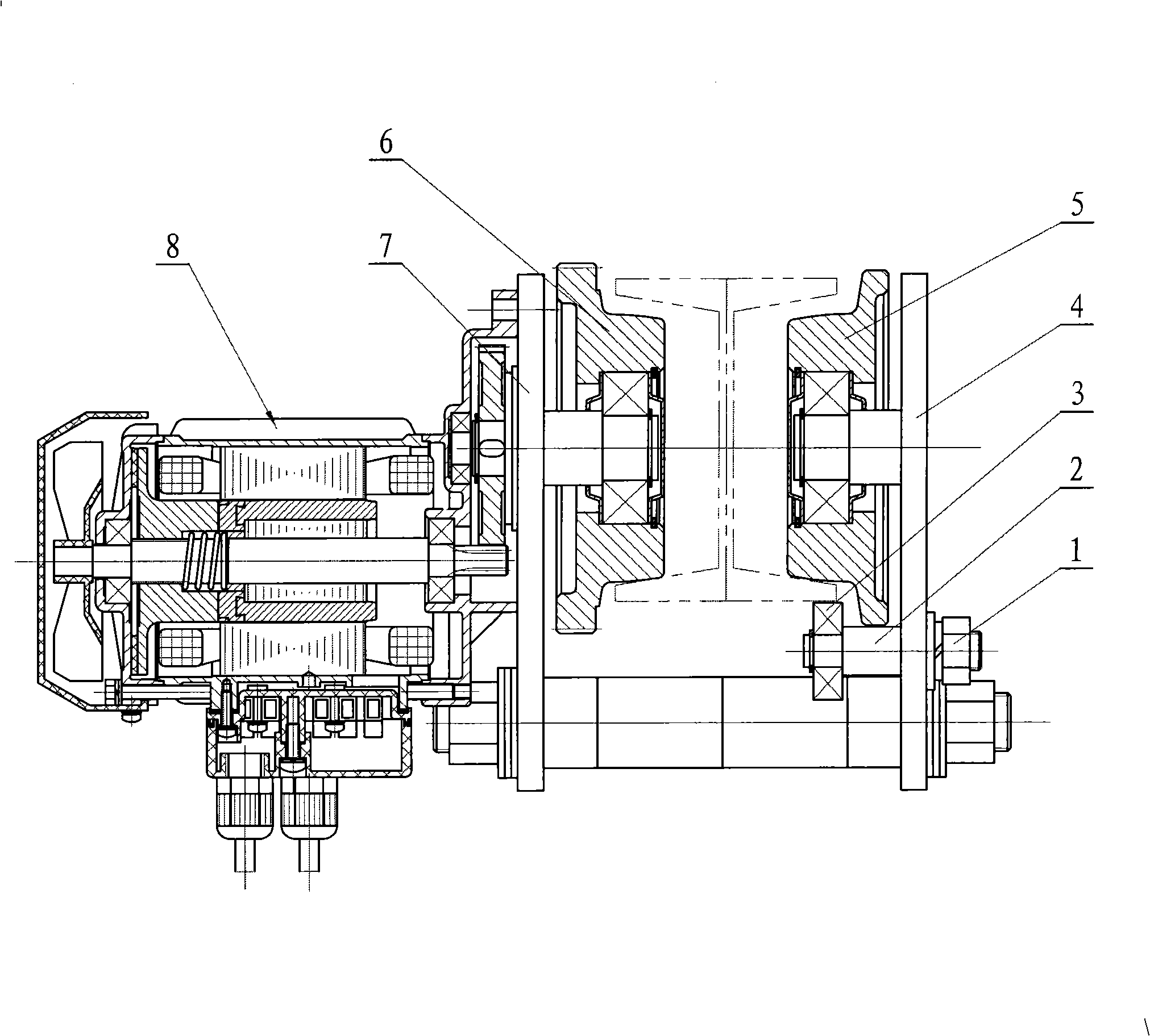
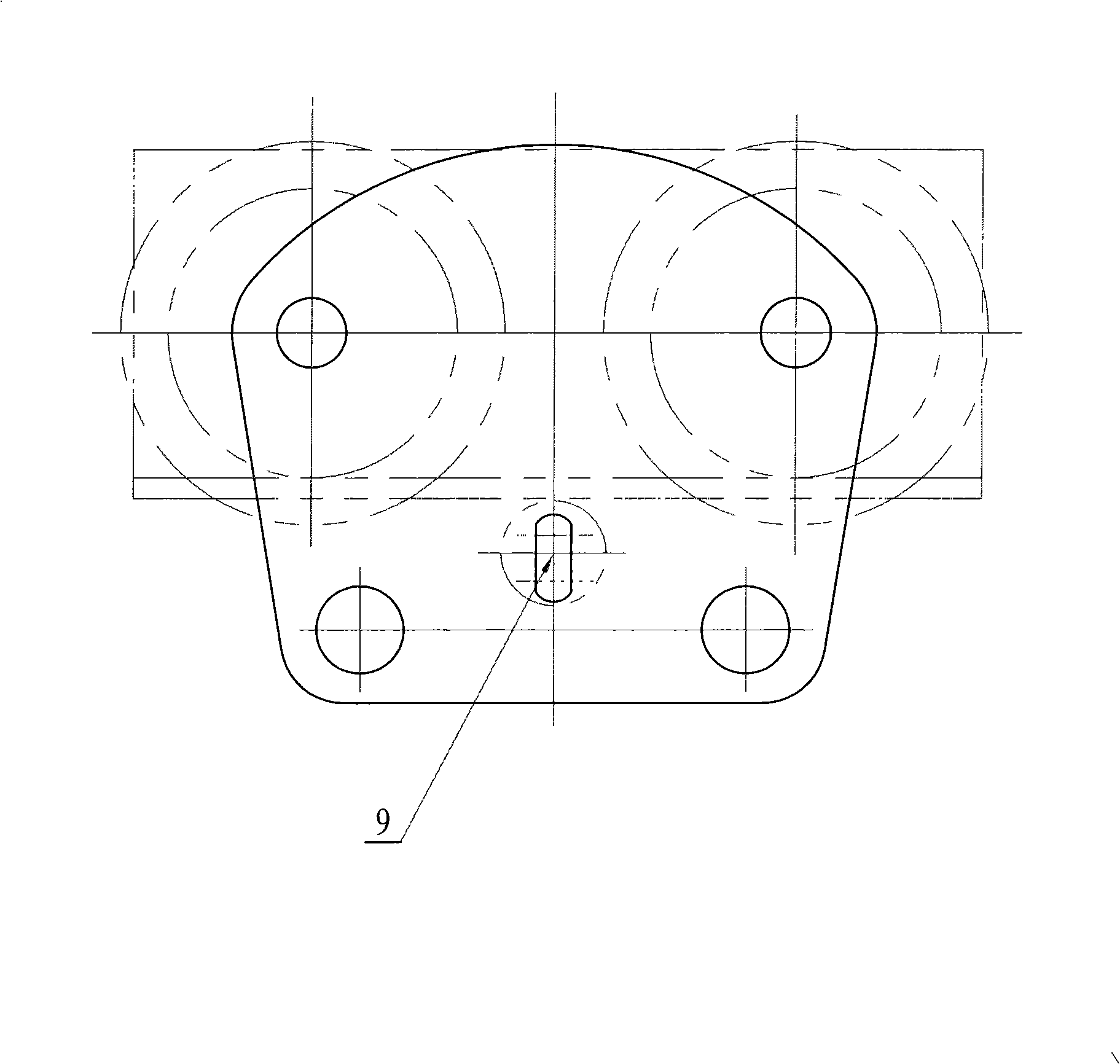
[0010] Such as figure 1 with figure 2 As shown, a single-phase miniature electric vehicle includes a fastening nut 1, a support shaft 2, a balance wheel 3, a driven wheel mounting plate 4, a driven wheel 5, a driving wheel 6, a driving wheel mounting plate 7, and a motor reducer 8 . The driving wheel 6 and the driven wheel 5 in the present embodiment are each provided with two, respectively arranged side by side on the driving wheel mounting plate 7 and the driven wheel mounting plate 4, the motor reducer 8 is installed on the driving wheel mounting plate 7, and the driving wheel 6 is in transmission connection with the motor reducer 8, and the driving wheel 6 and the driven wheel 5 respectively roll and cooperate with the left and right sides of the upper surface of the guide rail. The two mounting plates are arranged parallel to each other and a connecting shaft is arranged between them, and the two ends of the connecting shaft are fixedly connected with the driving wheel...


PUM


Abstract

The invention discloses a single-phase miniature electric travelling crane, comprising a driving wheel, a driven wheel and a motor speed reducer. The driving wheel and the driven wheel are respectively arranged on a mounting board of the driving wheel and a mounting board of the driven wheel; the driving wheel is in transmission connection with the motor speed reducer; the motor speed reducer is fixed on the mounting board of the driving wheel; the driving wheel and the driven wheel are respectively in rolling fit with the left and right sides of the upper edge surface of a guide rail; a connecting piece is arranged between two mounting boards; the electric travelling crane is provided with a balance wheel; the balance wheel is in rolling fit with the lower edge surface of the side of the guide rail where the driven wheel is positioned; a supporting shaft of the balance wheel is fixed on the mounting board of the driven wheel; and a single-phase capacitance-operating bypassed magnetic braking type asynchronous motor is selected as the motor of the electric travelling crane, and has braking function. As the lower edge surface of the side of the guide rail where the driven wheel is positioned is provided with the balance wheel, after the guide rail applies a downward acting force to the balance wheel, the acting force acts on the mounting board of the driven wheel, and is just balanced with the dead weight of the motor speed reducer on the mounting board of the driving wheel, thus a balancing iron block does not need to be arranged on one side of the mounting board of the driven wheel in order to balance the dead weight of the motor speed reducer. As the single-phase capacitance-operating bypassed magnetic braking type asynchronous motor is selected and has the braking function, the electric travelling crane is steady, safe and reliable in operation.

Description

technical field [0001] The invention relates to a conveying device, in particular to a single-phase miniature electric vehicle. Background technique [0002] The electric trolley is a rail-type conveying device, which is driven by a motor, has low noise, simple structure, and is easy to use. It is widely used in various places. The structure of the existing electric vehicle is generally provided with two rows of rollers on the left and right, one row of rollers is driven by a motor, and the other row of rollers is a passive wheel, and the driving wheel and the driven wheel are respectively installed on the driving wheel mounting plate and the passive wheel. On the board, the two mounting plates are fixedly connected by connecting shafts. The driving wheel and the driven wheel frame are rollingly matched with the guide rail on the guide rail. The guide rail is generally made of I-shaped steel. Rolling along the side surface, the driving wheel mounting plate of the electric t...

Claims


Application Information

Patent Timeline
IPC IPC(8): B66C9/16B66C9/14B66C9/08B66C9/00
Inventor 黄建民王建科林剑
Owner BADA MECHANICAL & ELECTRICAL
Why Eureka
Try Eureka