
Burner

A burner and pipeline technology, which is applied in the field of burners, can solve problems such as changing the flame and the influence of the roasting quality of the materials used to make cement.

Inactive Publication Date: 2009-01-21
FIVES PILLARD
View PDF3 Cites 2 Cited by
  • Summary
  • Abstract
  • Description
  • Claims
  • Application Information

AI Technical Summary

Problems solved by technology

[0004] The disadvantage of this type of burner is that it is relatively difficult to vary the characteristics of the flame over a wide range and to control it, but, especially in cement kilns, these characteristics have a very large influence on the firing quality of the material used to make cement

Method used


Image

  • Burner
  • Burner
  • Burner

Examples


Embodiment Construction

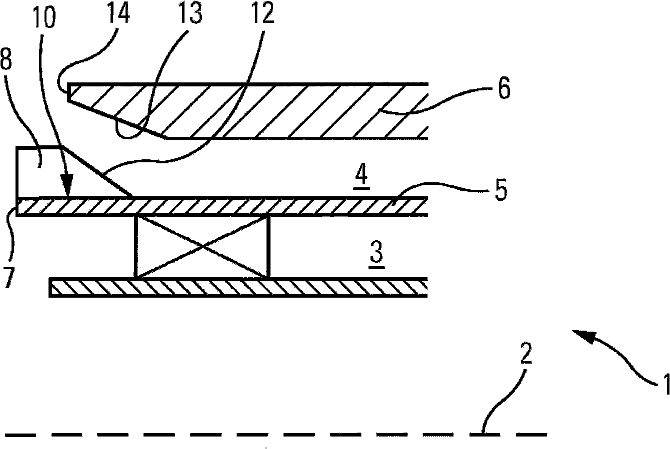
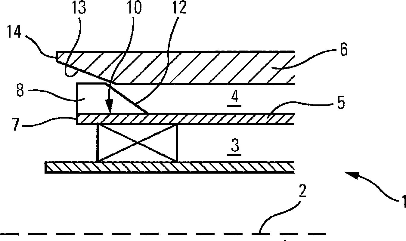
[0013] figure 1 A part of a burner 1 is shown which extends along an axis 2 and generally comprises a solid and / or fluid and / or gaseous fuel supply line and a central air delivery line which is used to make the The flame can be fixed to the flame holder and the central air delivery line can be cooled.

[0014] In the present example, the burner 1 also comprises a tangential primary air supply peripheral line 3 surrounding the central air supply line and all fuel supply lines. This tangential primary air supply peripheral line 3 comprises means capable of imparting a tangential component to the air flow at its outlet. On the other hand, preferably, the tangential flow air supply line 3 corresponds to any one disclosed in the two patent applications FR 2,887,597 and FR 06 04,829.

[0015] The burner 1 also comprises an axial primary air supply peripheral line 4 whose outlet is such that the air flows substantially axially, i.e. without a tangential component (or at least its t...


PUM


Abstract

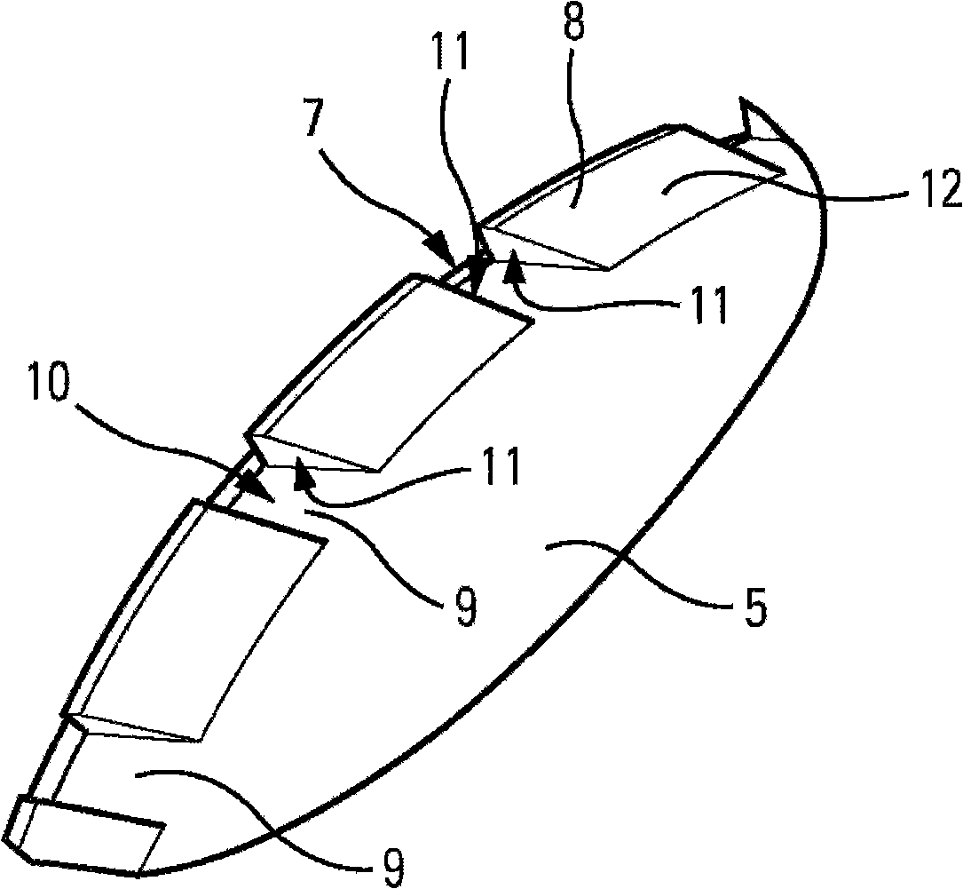
The invention relates to a burner (1) which comprises an air supply annular tube (4) limited by two coaxial conduits (5, 6) that can move relative to each other along the axis between the open position and the close position. The conduit (5) has an annular flange (8) comprising an axial groove. According to the invention, the flange (8) is disposed on the downstream end (7) of the conduit (5); the second conduit (6) comprises a closure part (13). While the conduits (5, 6) is on the open position, the distance between closure part (13) and the flange (8) is large enough for a great deal of air to pass through; while the conduits (5, 6) is on the close position, the distance is almost zero to make all the air pass through the groove.

Description

technical field [0001] The present invention relates to a burner, in particular, the present invention relates to a burner for a cement plant. Background technique [0002] A burner is known which extends along an axis and comprises an axial primary air supply annular line surrounding all fuel supply lines and which consists of an inner duct extending along the axis of the burner and a An outer conduit is defined wherein both conduits are axially movable relative to each other during translation in the axial direction between an open position and a closed position. [0003] Such a burner is disclosed for example in patent application EP 967,434, which is commonly used in cement plants and comprises two primary air supply lines surrounding all fuel supply lines of the burner. These two lines are the axial flow air supply line and the tangential flow air supply line. The air flow at the outlet of the axial flow air supply line is parallel to the axis of the burner and may hav...

Claims


Application Information

Patent Timeline
IPC IPC(8): F23D14/22
CPCF23D17/002F23C7/008F23D2900/11402
Inventor 路易斯·里奇格尔·勒·皮韦尔
Owner FIVES PILLARD
Learn More