Polishing head, edge controlling loop thereof as well as method for increasing velocity of crystal edge polishing

A technology of edge control and polishing rate, applied in surface polishing machine tools, grinding/polishing equipment, manufacturing tools, etc., can solve the problems of limited crystal edge polishing rate and crystal edge residue, so as to improve crystal edge residue and improve polishing speed effect

Inactive Publication Date: 2009-01-28
UNITED MICROELECTRONICS CORP
View PDF2 Cites 2 Cited by
  • Summary
  • Abstract
  • Description
  • Claims
  • Application Information

AI Technical Summary

Problems solved by technology

However, the edge polishing rate it can improve is still very limited, and the problem of edge residue still exists

Method used


Image

  • Polishing head, edge controlling loop thereof as well as method for increasing velocity of crystal edge polishing
  • Polishing head, edge controlling loop thereof as well as method for increasing velocity of crystal edge polishing
  • Polishing head, edge controlling loop thereof as well as method for increasing velocity of crystal edge polishing

Examples


Embodiment Construction

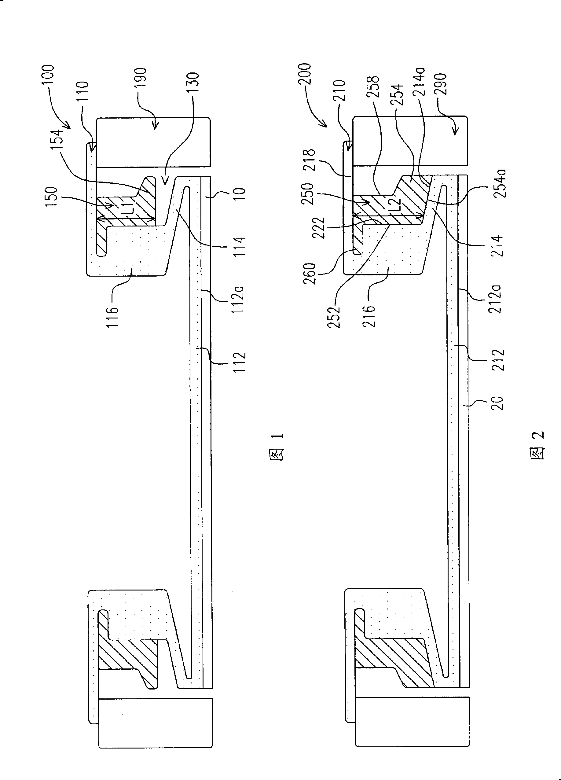
[0084] The inventor found that the key to the insufficient polishing rate of the crystal edge of the prior art shown in Figure 1 and the inability of US 6,979,250 and US 6,776,694 to effectively solve the insufficient polishing rate of the crystal edge is that the bottom surface of the edge control ring and the lip of the flexible film The outer surfaces of the parts have gaps between each other when they are not yet inflated. When the flexible film is inflated, there is a gap between the lip and the contact bottom surface of the edge control ring, so it will be lifted upwards, so that the load provided to the edge is reduced or eliminated, resulting in insufficient polishing rate for edge polishing.

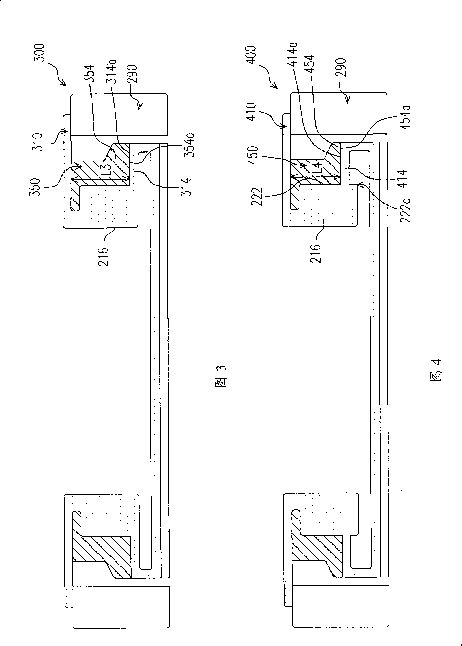
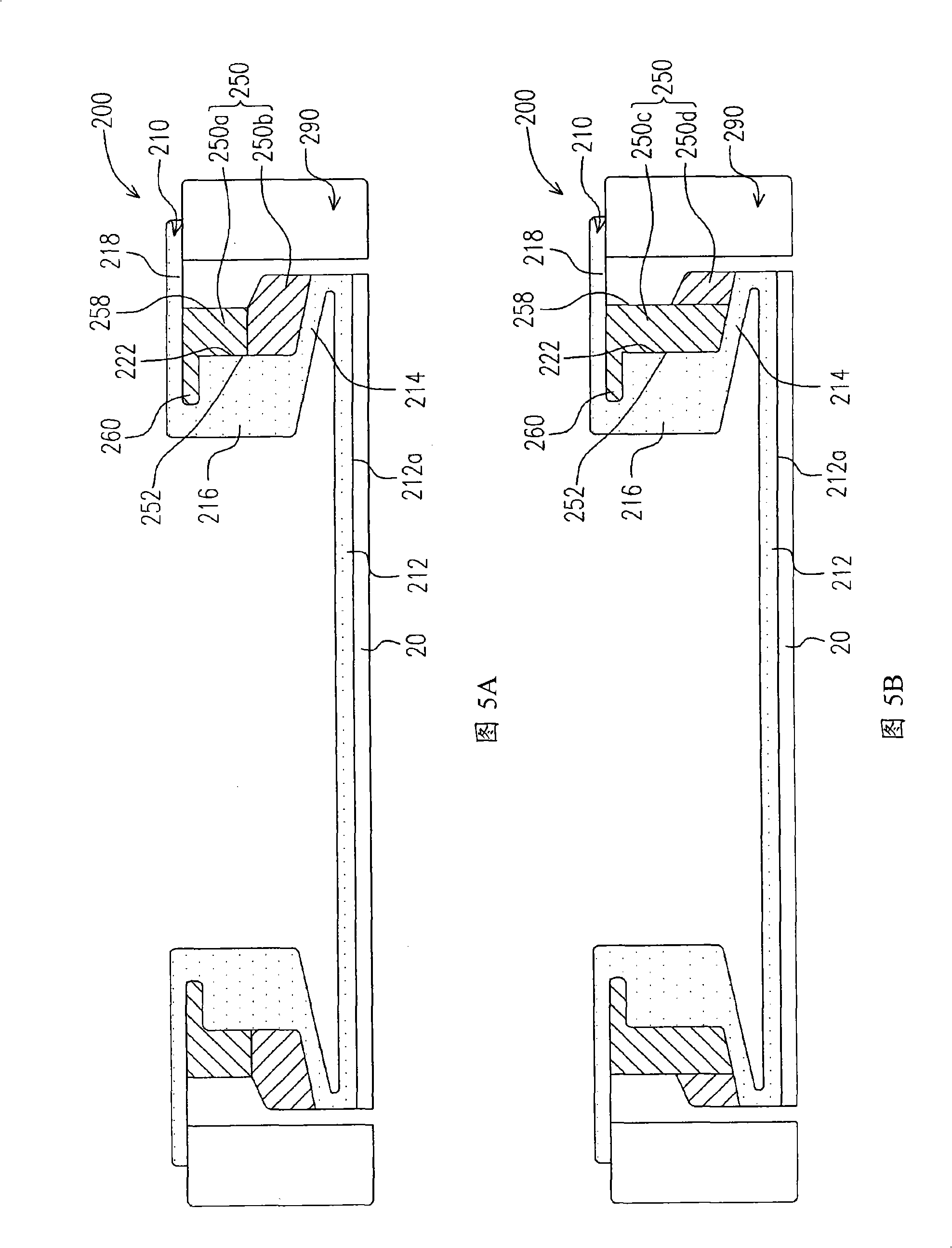
[0085] The present invention proposes several methods that can increase the crystal edge load for this discovery, which mainly makes the contact bottom surface of the edge control ring of the polishing head and the outer surface of the lip of the flexible film contact each other ...


PUM


Abstract

The invention discloses a polishing head which is suitable for the polishing process of chemical machines and comprises a fixed ring, a flexible film and an edge control ring; wherein, the fixed ring is used for fixing wafers; the flexible film comprises a lip part and a bottom part which are connected with each other; a bottom surface of the bottom part is attached to the wafers; the edge control ring comprises a bottom part which is provided with a contact bottom surface; the contact bottom surface and an external surface of the lip part of the flexible film are mutually attached when the flexible film is not aerated.

Description

technical field [0001] The present invention relates to a semiconductor process device, and in particular to a polishing head of a chemical mechanical polishing device and its edge control ring, and a method for increasing the polishing rate of crystal edges. Background technique [0002] The chemical mechanical polishing process is a planarization method widely used at present. A typical planarization method is to hold the wafer on a polishing head. Then, the surface of the wafer to be polished is positioned facing the rotating polishing pad. During polishing, the polishing head provides back pressure to the wafer, and the polishing pad usually supplies slurry. Through the relative movement of the wafer and the polishing pad, the wafer can be planarized by chemical force and mechanical force at the same time. [0003] With the evolution of technology generations, various improved or new chemical mechanical polishing devices have emerged. In addition to the extensive rese...

Claims


Application Information

Patent Timeline
Patent Type & Authority Applications(China)
IPC IPC(8): B24D13/14B24B29/00B24B1/00H01L21/304
Inventor 吴昌信杨子弘陈少伟刘伊津杨渝翔郭沛琳施惠绅
Owner UNITED MICROELECTRONICS CORP
Why Eureka
Try Eureka