
Development of print plates in offset printers

A printing machine, printing mechanism technology, applied in the direction of lithographic rotary printing machine, printing machine, rotary printing machine, etc., can solve the problem of not being able to see the solution, and achieve the effect of reliable removal

Inactive Publication Date: 2013-03-20
HEIDELBERGER DRUCKMASCHINEN AG
View PDF1 Cites 0 Cited by
  • Summary
  • Abstract
  • Description
  • Claims
  • Application Information

AI Technical Summary

Problems solved by technology

A solution to this problem cannot be seen from patent document US 2007 / 0095232 A1

Method used


Image

  • Development of print plates in offset printers
  • Development of print plates in offset printers
  • Development of print plates in offset printers

Examples


Embodiment Construction

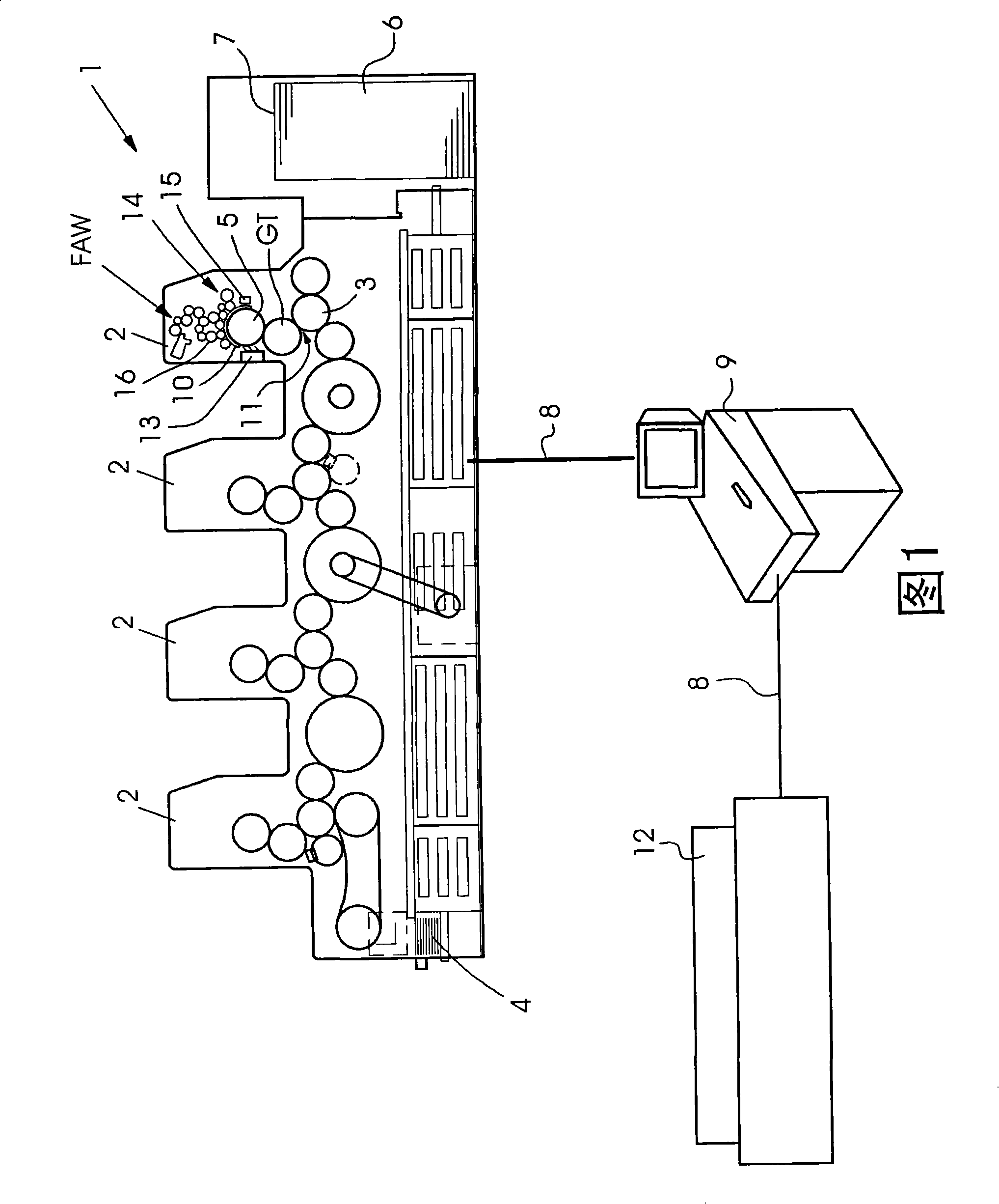
[0027] figure 1 A sheet-fed offset printing press 1 with four printing units 2 is depicted in FIG. Each of the four printing units 2 is provided with an inking unit FAW and a dampening unit 14 . During the printing operation, printing ink is applied to the plate cylinder 5 in the printing unit 2 by the inking unit FAW via the ink roller 16 . In order to be able to influence the consistency of the printing ink in the inking unit FAW, each printing unit 2 also has a dampening unit 14 . The dampening unit 14 delivers dampening agent to the inking unit FAW so that the consistency of the ink can be changed thereby. The inking unit FAW and the dampening unit 14 can be pressed separately onto the plate cylinder 5, the dampening unit 14 and the inking unit FAW can also be pressed away from each other. The printing form cylinder carries a printing form 10 which contains the color separations for the corresponding printing unit 2 . The color separations on the printing plates 10 of ...


PUM


Abstract

The method involves loading a non-processed printing plate (10) on a printing unit (2) of a printing machine (1) before starting printing process, where the printing plate is exposed outside the printing machine. The non-processed printing plate is moistened by a moistening unit for exposure time that corresponds to one and half times time interval or number of machine revolutions that are provided by utilization of a pre-processed printing plate in the same printing machine before starting the printing process. An independent claim is also included for a printing machine.

Description

technical field [0001] The invention relates to a device and a method for developing printing plates in a printing press having at least one printing unit. Background technique [0002] In offset printing presses, printing formes are provided in the individual printing units, which carry the printed image for a color separation. To apply a printing image on a printing plate, the printing plate is imaged according to color separations. The printing plate is imaged during an exposure process, which can be performed, for example, by means of a laser. Exposure by the printing plate changes the later printed or later non-printed areas. The unexposed and unimaged areas then have to be processed in a development step in order to finally produce different surface properties for the unimaged and imaged areas. In this case, after the development process, the unimaged areas are usually treated such that these areas are ink repellent, while the imaged areas of the printing plate are ...

Claims


Application Information

Patent Timeline
Patent Type & Authority Patents(China)
IPC IPC(8): B41C1/10B41N3/08B41F7/24
CPCB41C1/1075B41N3/08G03F7/3035
Inventor T·贝歇贝格尔M·迪策A·豪克N·普法伊费尔
Owner HEIDELBERGER DRUCKMASCHINEN AG
Learn More