Main power system of concrete delivery pump and concrete delivery pump

A technology of a concrete delivery pump and a main power system, applied in the field of concrete machinery, can solve the problems of wasting main oil pump resources, incapable of fully exerting the oil pumping capacity of the main oil pump, increasing the manufacturing cost of the concrete delivery pump, etc. The effect of oil discharge flow and increased displacement

Active Publication Date: 2009-01-28
SANY AUTOMOBILE MFG CO LTD
View PDF1 Cites 5 Cited by
  • Summary
  • Abstract
  • Description
  • Claims
  • Application Information

AI Technical Summary

Problems solved by technology

Although this can directly increase the amount of hydraulic oil pumped by the main oil pump, it ignores the problem that the pumping capacity of the main oil pump cannot be fully utilized
Because the rated speed of the motor is relatively low, generally only 1480 rpm, and the maximum working speed of the main oil pump in the concrete delivery pump is generally 2000 rpm, therefore, in the concrete delivery pump with the motor as the power source, the moto

Method used


Image

  • Main power system of concrete delivery pump and concrete delivery pump
  • Main power system of concrete delivery pump and concrete delivery pump
  • Main power system of concrete delivery pump and concrete delivery pump

Examples


Embodiment 1

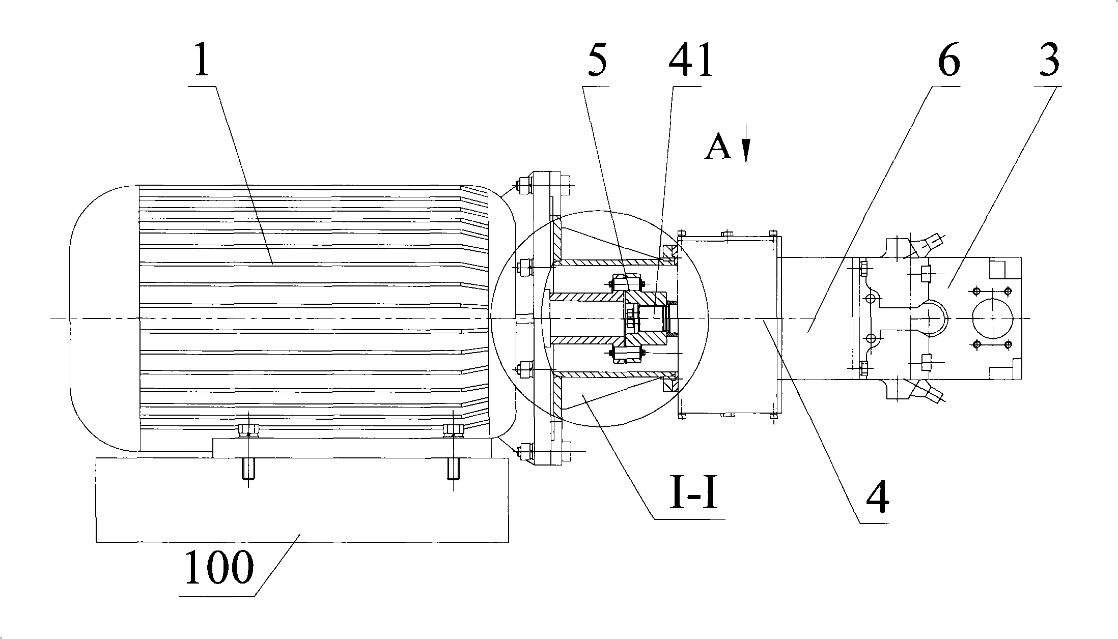
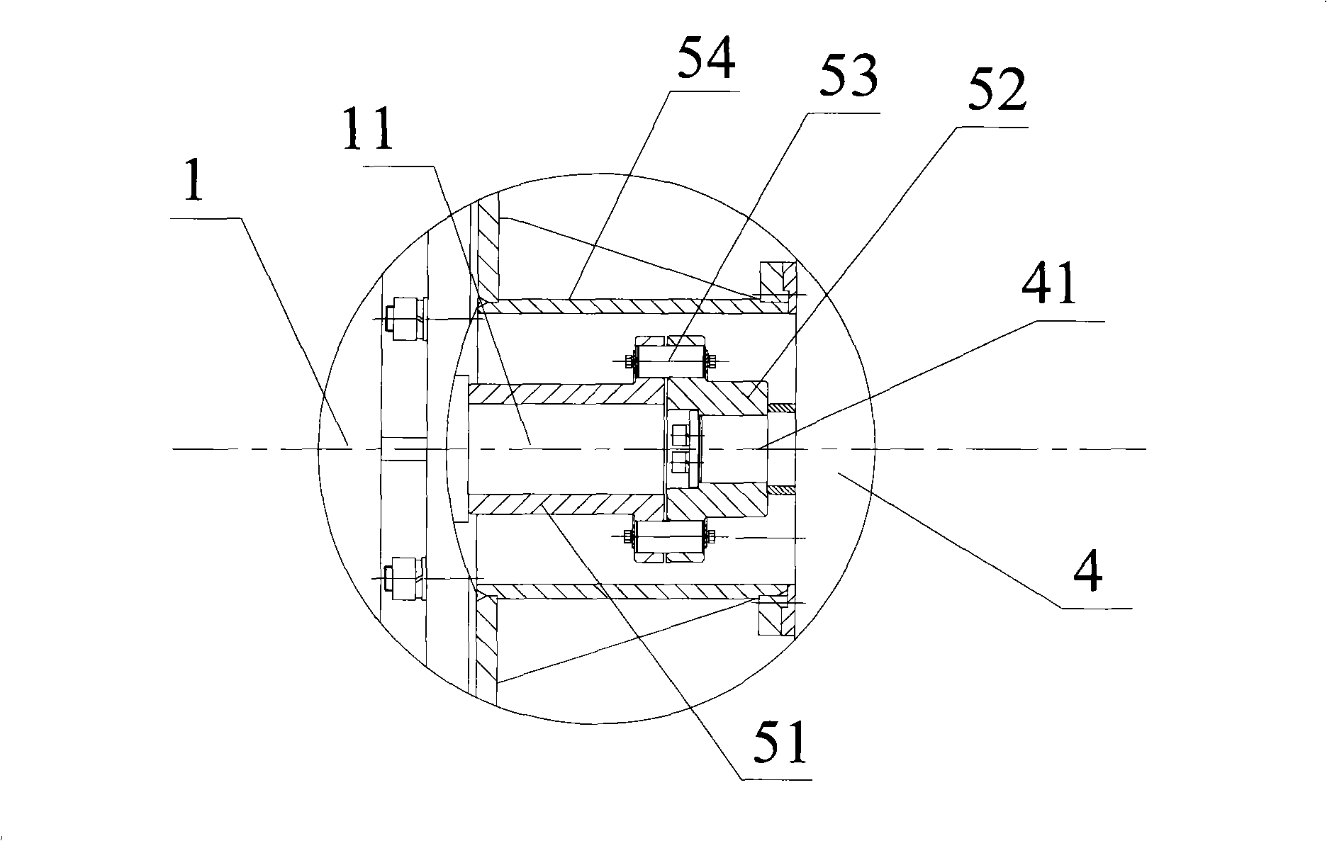
[0044] Embodiment 1 provides an active power system of a concrete delivery pump that uses gear transmission to increase speed, such as figure 2 As shown, the main power system of the concrete delivery pump provided in this example includes the motor 1, the first hydraulic pump 3, the couplings 5, 6, and the speed increaser 4. For the sake of clarity, the figure also shows the base 100, so The main power system of the concrete delivery pump described above is fixed on the base 100. Generally, the main power system of the concrete delivery pump includes a main oil pump and an auxiliary oil pump. In this example, the main oil pump includes the first hydraulic pump 3, and the first hydraulic pump 3 includes the first pump axis (not shown). In this example, in order to reduce the cost of the main power system of the concrete delivery pump, the first hydraulic pump 3 is a single hydraulic pump. The structure of the shaft coupling 5 or 6 and the speed increaser 4 will be described ...


PUM


Abstract

The invention discloses a main power system of a concrete pump. The main power system of the concrete pump comprises a motor, a main oil pump, a coupler and a speed increaser, wherein, the speed increaser comprises a speed increaser shell, an input shaft, an output shaft, a driving wheel and a driven wheel; the driving wheel arranged on the input shaft can drive the driven wheel arranged on the output wheel to rotate; the transmission ratio of the driving wheel to the driven wheel is smaller than 1; the coupler comprises a coupler and a coupler; the coupler connects a power shaft of the motor and the input shaft of the speed increaser; the coupler connects the output shaft of the speed increaser and a pump shaft of the main oil pump. The preferential technical proposal is that: the driving wheel and the driven wheel of the speed increaser are set into gear wheels that are mutually meshed; the transmission ratio of the driving wheel to the driven wheel is set to be 0.6 to 0.8. The main power system of the concrete pump provided by the invention can cause the main oil pump to work at a relatively high speed, fully exerts the oil pumping function of the main oil pump and increases the output of the main oil pump.

Description

technical field [0001] The invention relates to a concrete machine, in particular to an active power system of a concrete delivery pump and the concrete delivery pump. Background technique [0002] Concrete delivery pump is a kind of equipment in cement concrete machinery, which is used to deliver concrete in vertical or horizontal direction. Concrete pumps have been widely used in the modern construction industry because of their high efficiency, high degree of mechanization, ability to adapt to different operating environments and less environmental pollution. [0003] Concrete delivery pumps generally include hoppers, pumping systems, delivery pipelines, main power systems and other related parts. The hopper is used to hold or temporarily store concrete; the pumping system is used to pump the concrete in the hopper to the delivery pipeline. Generally speaking, the pumping system includes two hydraulic cylinders, which use the alternate reciprocating motion of the pistons...

Claims


Application Information

Patent Timeline
IPC IPC(8): F04B15/02F04B17/03E04G21/02
Inventor 易小刚易秀明杨新华李永维高杨
Owner SANY AUTOMOBILE MFG CO LTD
Why Eureka
Try Eureka