Probe for measuring pipe wall thickness

A technology of wall thickness measurement and pipe wall, which is applied in the field of special probes, can solve the problems of wasting materials, prolonging the detection time, and long construction period, so as to save time, reduce operation steps, and improve efficiency

Inactive Publication Date: 2009-01-28
中海油人力资源服务有限公司
View PDF0 Cites 7 Cited by
  • Summary
  • Abstract
  • Description
  • Claims
  • Application Information

AI Technical Summary

Problems solved by technology

[0002] Pipeline is an important facility used to transport oil, natural gas and other fluids in petroleum and other industries. It is necessary to regularly detect the wall thickness of some parts of the pipeline to prevent leakage due to corrosion and wear and thinning of the pipe wall. However, existing detection methods In general, it is necessary to remove the outer insulation layer of the pipeline to be tested, then apply coupling agent, and then use an ultrasonic probe to measure. The defect of this method is that the damaged area of ​​the outer insulation layer is large, and it is not easy to recover after the inspection. It is easy, wastes materials, prolongs the detection time, so the cost is high and the construction period is long, and it is difficult to track and detect the same detection point. Only by monitoring the thickness of the same pipe position can the pipe strength be more scientifically wait for assessment
Therefore, the inventor invented the method of drilling a small hole on the insulation layer of the pipeline to be detected, and inserting the ultrasonic probe into the small hole for detection, but the existing probe needs to be modified to apply this method

Method used


Image

  • Probe for measuring pipe wall thickness
  • Probe for measuring pipe wall thickness
  • Probe for measuring pipe wall thickness

Examples


Embodiment Construction

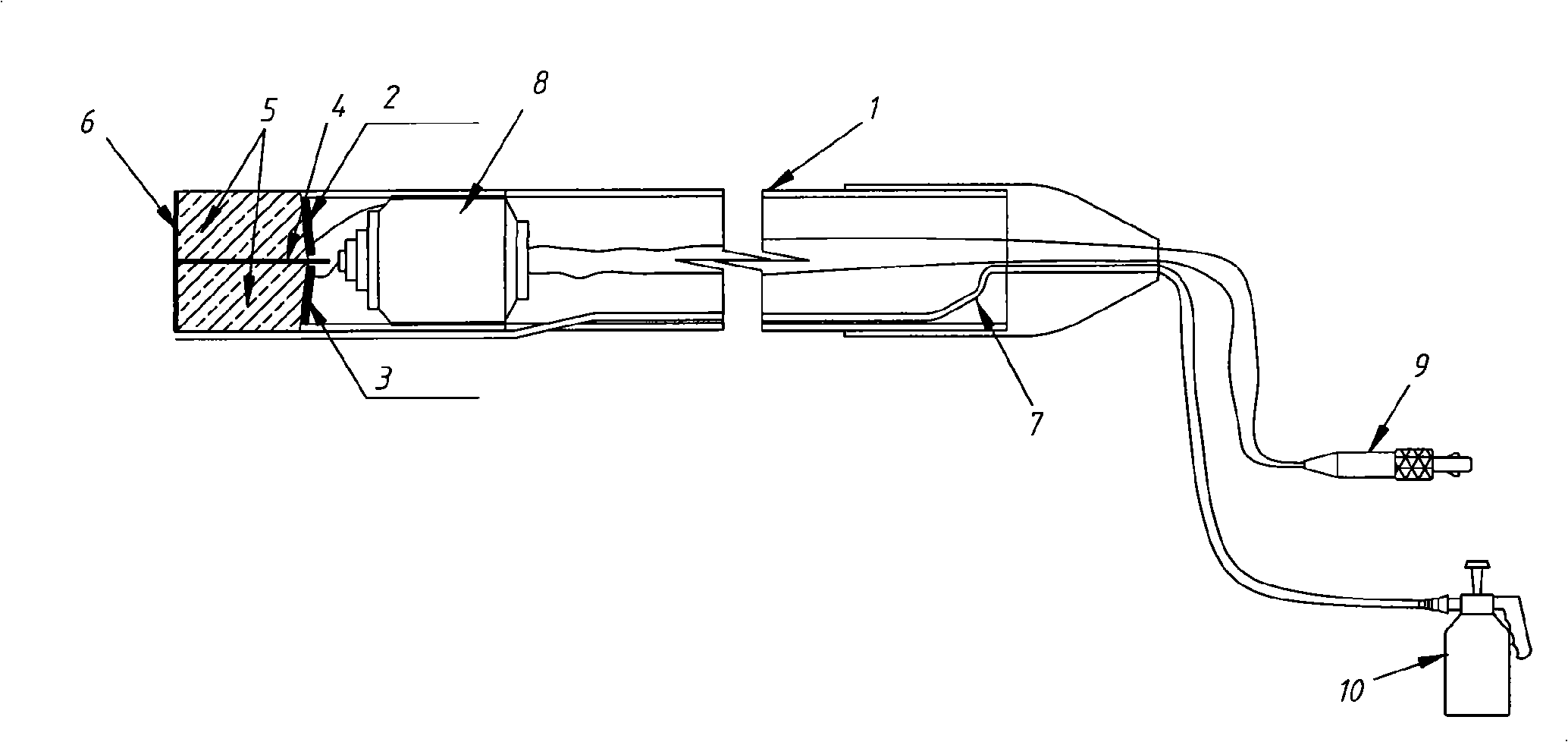
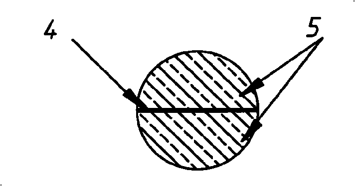
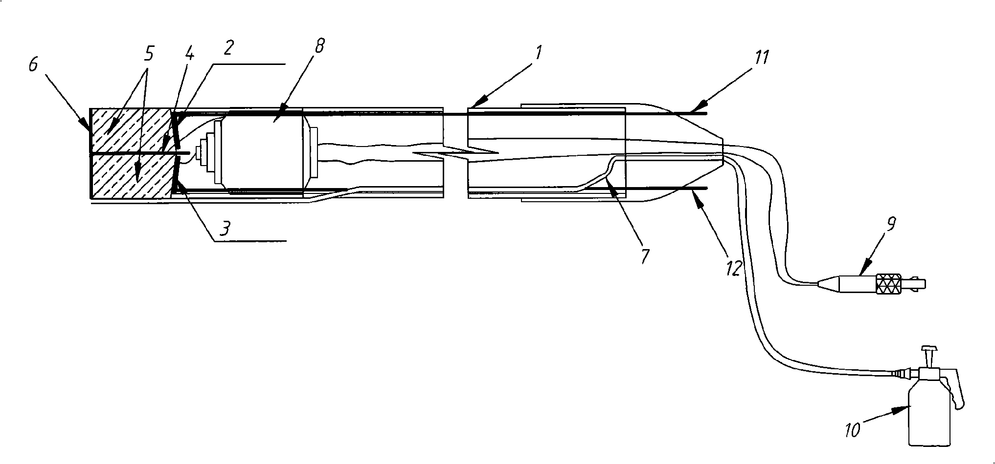
[0012] figure 1 It is a structural schematic diagram of a specific embodiment of the present invention, such as figure 1 As shown, the pipe wall thickness measuring probe includes a casing 1, an ultrasonic emitting crystal 2, an ultrasonic receiving crystal 3, a separation layer 4, a damping block 5, a protective film 6, and a couplant delivery tube 7. The crystal 2 and the ultrasonic receiving crystal 3 are located in the front part of the shell 1. The ultrasonic emitting crystal 2 and the ultrasonic receiving crystal 3 are connected to a joint 8 through a signal connection line, and then connected to an external connection joint 9 by a signal connection line, and finally connected to the ultrasonic measuring device. On the thickness meter, a damping block 5 is also respectively provided in front of the ultrasonic transmitting crystal 2 and the ultrasonic receiving crystal 3, combined with figure 2 As shown, the separation layer 4 separates the ultrasonic transmitting cryst...


PUM


Abstract

The invention discloses a probe head for measuring the thickness of a tube wall, which comprises a shell, an ultrasonic transmitting crystal, an ultrasonic receiving crystal, a separate layer, damping blocks, a protective film and a couplant delivery pipe. The shell takes the shape of a narrow and long circular tube, and the ultrasonic transmitting crystal and the ultrasonic receiving crystal are positioned in the interior front part of the shell and are connected to an external joint by a signal connecting line after being connected to a joint by the signal connecting line. The front sides of the ultrasonic transmitting crystal and the ultrasonic receiving crystal are respectively provided with one damping block, and the separate layer separates the ultrasonic transmitting crystal, the ultrasonic receiving crystal and two damping blocks. The protective film is arranged on a front shell end face of the damping block. The couplant delivery pipe is a long and thin pipe with one end positioned outside the shell and parallel and level to the front end face of the shell while the other end is connected with an external couplant delivery holder. The probe head of the invention can realize the tracking monitoring the same position; simultaneously, couplant spraying and detection are not required for separately carrying out, thus saving time and improving efficiency further.

Description

technical field [0001] The invention relates to pipeline detection equipment, in particular to a special probe for detecting pipeline wall thickness. Background technique [0002] Pipeline is an important facility used to transport oil, natural gas and other fluids in petroleum and other industries. It is necessary to regularly detect the wall thickness of some parts of the pipeline to prevent leakage due to corrosion and wear and thinning of the pipe wall. However, the existing detection methods In general, it is necessary to remove the outer insulation layer of the pipeline to be tested, then apply coupling agent, and then use an ultrasonic probe to measure. The defect of this method is that the damaged area of ​​the outer insulation layer is large, and it is not easy to recover after the inspection. It is easy, wastes materials, prolongs the detection time, so the cost is high and the construction period is long, and it is difficult to track and detect the same detection ...

Claims


Application Information

Patent Timeline
Patent Type & Authority Applications(China)
IPC IPC(8): G01B17/02
Inventor 唐康林赵维众尹椅光李富华王品赵梦群王会群张立国
Owner 中海油人力资源服务有限公司
Why Eureka
Try Eureka