Color wheel

A color wheel and positioning ring technology, applied in the field of color wheels, can solve the problems of reduced lifespan, poor dynamic balance of color wheels, flying fan-shaped annular filter 11, etc., and achieve the effect of improving the lifespan

A color wheel and positioning ring technology, applied in the field of color wheels, can solve the problems of reduced lifespan, poor dynamic balance of color wheels, flying fan-shaped annular filter 11, etc., and achieve the effect of improving the lifespan

CN101354464AInactive Publication Date: 2009-01-28HONG FU JIN PRECISION IND (SHENZHEN) CO LTD +1

Image

  • Color wheel
  • Color wheel
  • Color wheel

Examples


Embodiment Construction

[0020] The present invention will be further described in detail below with reference to the accompanying drawings.

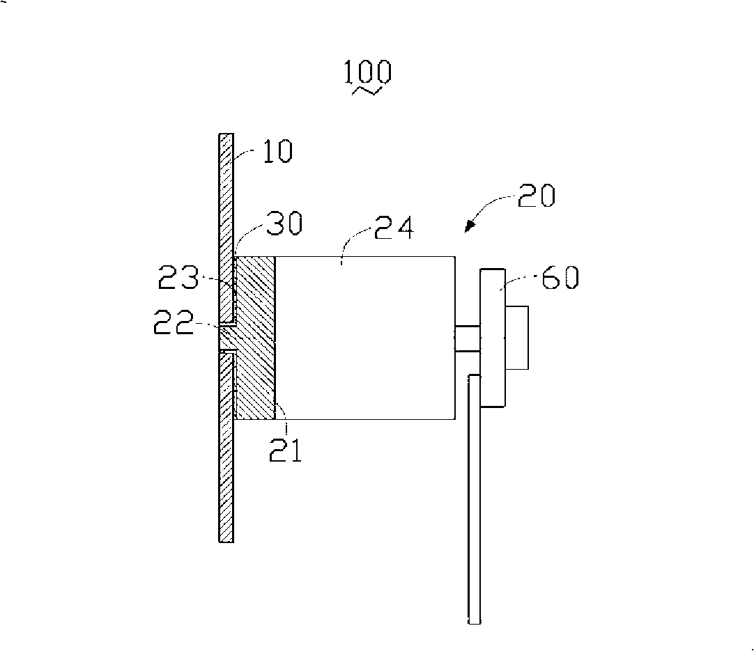
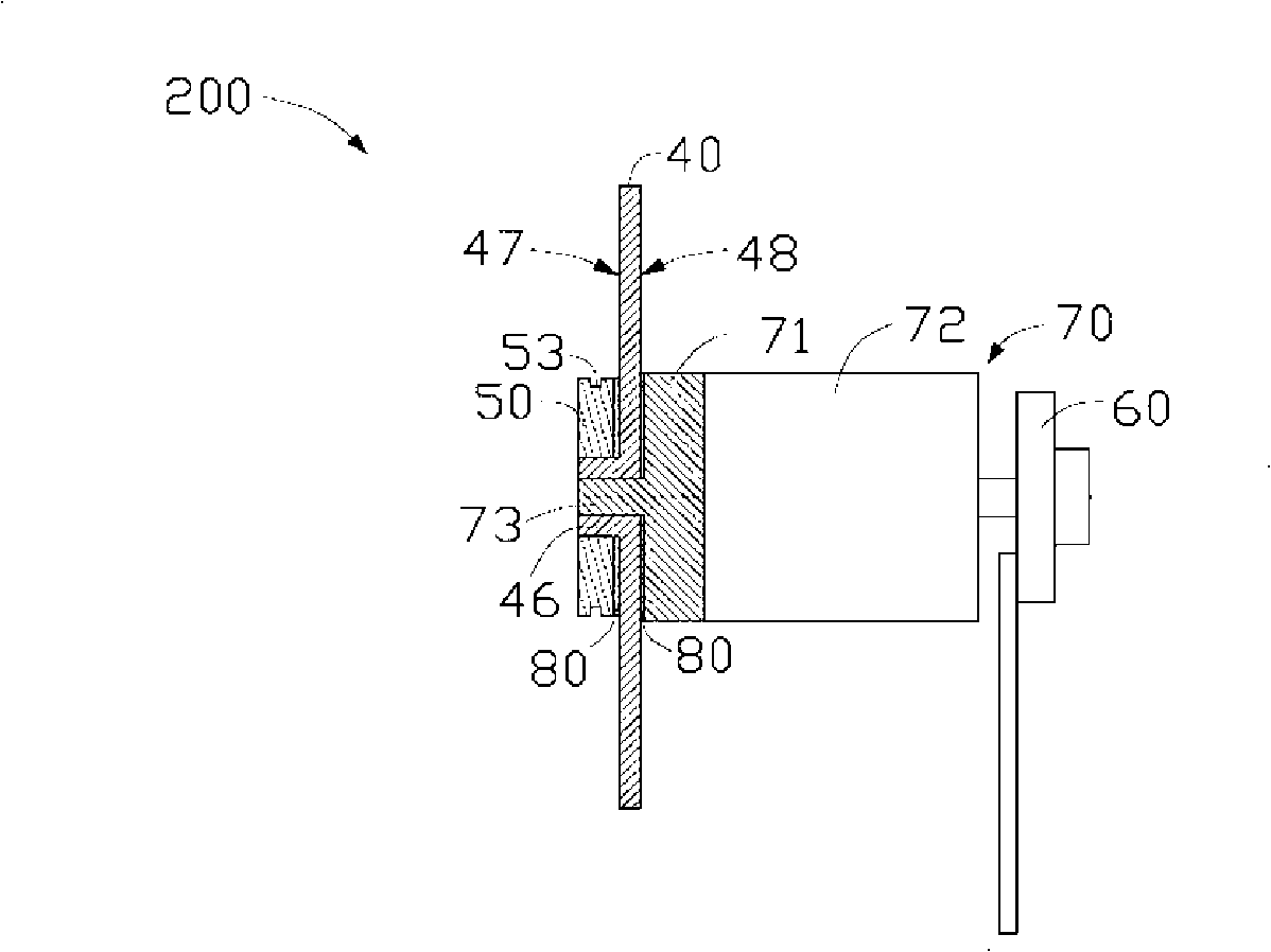
[0021] Please also refer to Figure 3 to Figure 5 The color wheel 200 according to the first embodiment of the present invention includes a motor 70 , a filter set 40 and a positioning ring 50 . The filter set 40 is sandwiched between the motor 70 and the positioning ring 50 .

[0022] The motor 70 is composed of a shaft cover 71 and a motor body 72 , the shaft cover 71 has a bearing surface 74 and a rotating shaft 73 , and the shaft cover 71 is disposed in the axial direction of the motor body 72 close to the motor body 72 . One side of the filter set 40.

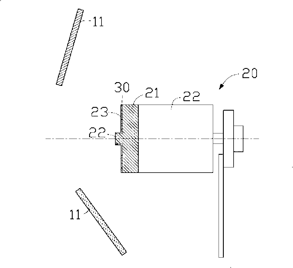
[0023] like Figure 5 As shown, the filter set 40 includes a plurality of adjoining and glued single-piece fan-shaped annular filters 41, each filter 41 is a transparent substrate made of glass material or quartz material and coated made. The filter set 40 further includes a first surface 47 in contact...


PUM


Abstract

The invention provides a colour wheel, comprising a motor with a rotation shaft, a filter group, and a positioning ring; the filter group comprises a plurality of filters which are adjacently attached to each other; the filter group is provided with a central hole which is sleeved with the rotation shaft of the motor; the central part of the positioning ring is provided with a through hole; each filter is provided with a convex platform which extends from the edge of the central hole to the circumference of the filter; each convex platform is adjacently attached to each other so as to form a convex platform group; the dimension of the convex platform group is corresponding to the through hole of the positioning ring; the convex platform group is clamped inside the through hole of the positioning ring. The colour wheel structure can prevent the filter from flying away.

Description

technical field [0001] The invention relates to a color wheel, in particular to a color wheel which can prevent the flying of optical filters. Background technique [0002] Projection system is a common type of optoelectronic display device, which is widely used in life entertainment, academic lectures, business presentations and other occasions. According to its display principle, projection system can be divided into cathode ray tube (CRT) projection system, liquid crystal display (LCD) projection system, digital light processing (Digital LightProcessing, DLP) projection system and silicon crystal (Liquid Crystal on Silicon, LCoS) projection system and other categories. Among them, the DLP projection system is favored by consumers due to its advantages of high brightness, vivid colors, high response rate, light and short devices, and occupies the main market of current projection system products. [0003] The DLP projection system uses a digital micro-mirror chip (Digita...

Claims


Application Information

Patent Timeline
28 Jan 2009
Publication
CN101354464A
IPC
G02B7/00; G03B21/14
CPC
G02B26/008; G02B7/006
Inventors
何侑伦