

Battery set
A technology for battery packs and battery cells, which is applied in battery pack components, secondary battery manufacturing, circuits, etc., can solve problems such as being unfavorable for application and increasing the overall weight of the battery pack, and achieve the effect of avoiding battery pack disconnection.
- Summary
- Abstract
- Description
- Claims
- Application Information
AI Technical Summary
Problems solved by technology
Method used
Image

Examples
specific Embodiment 1
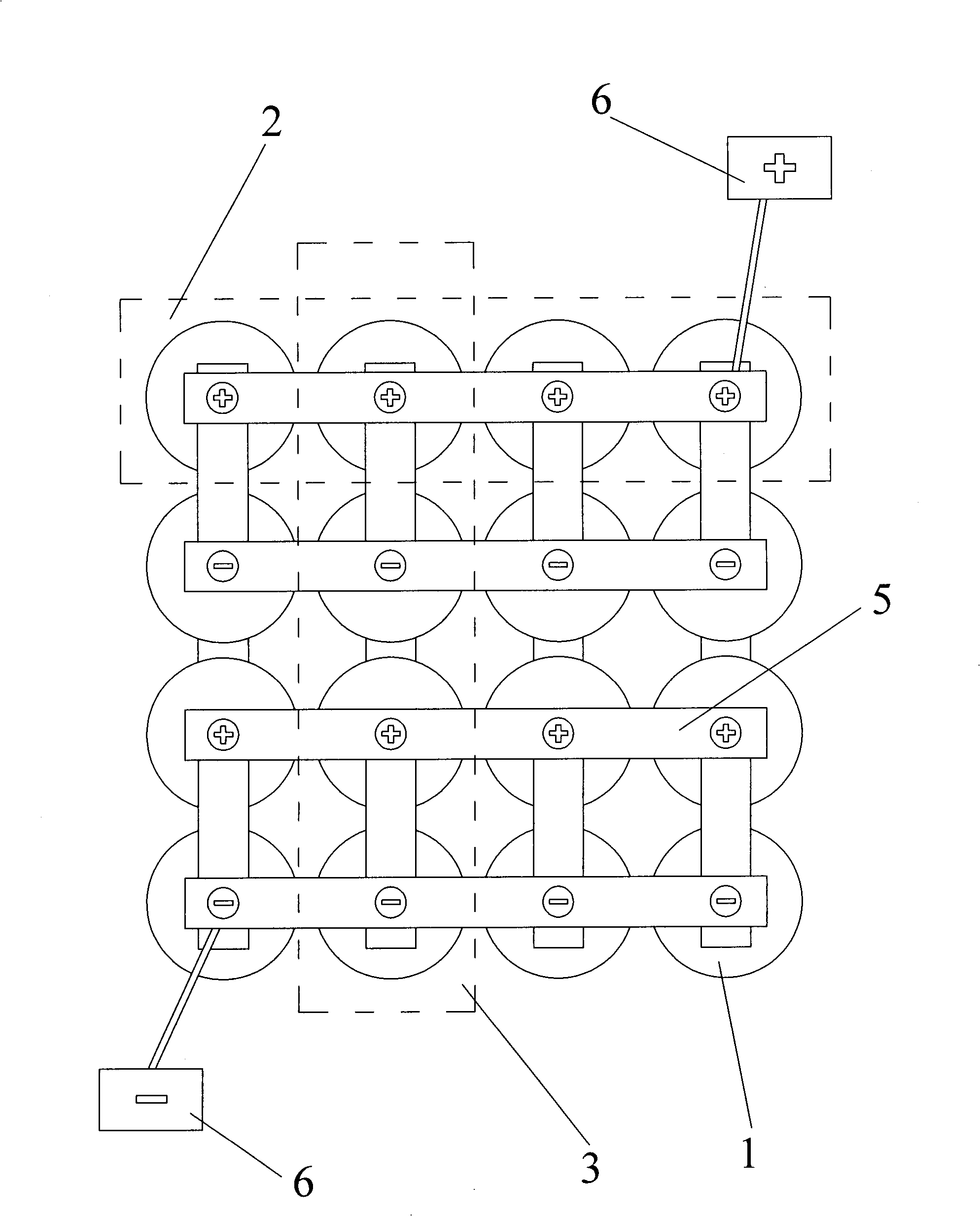
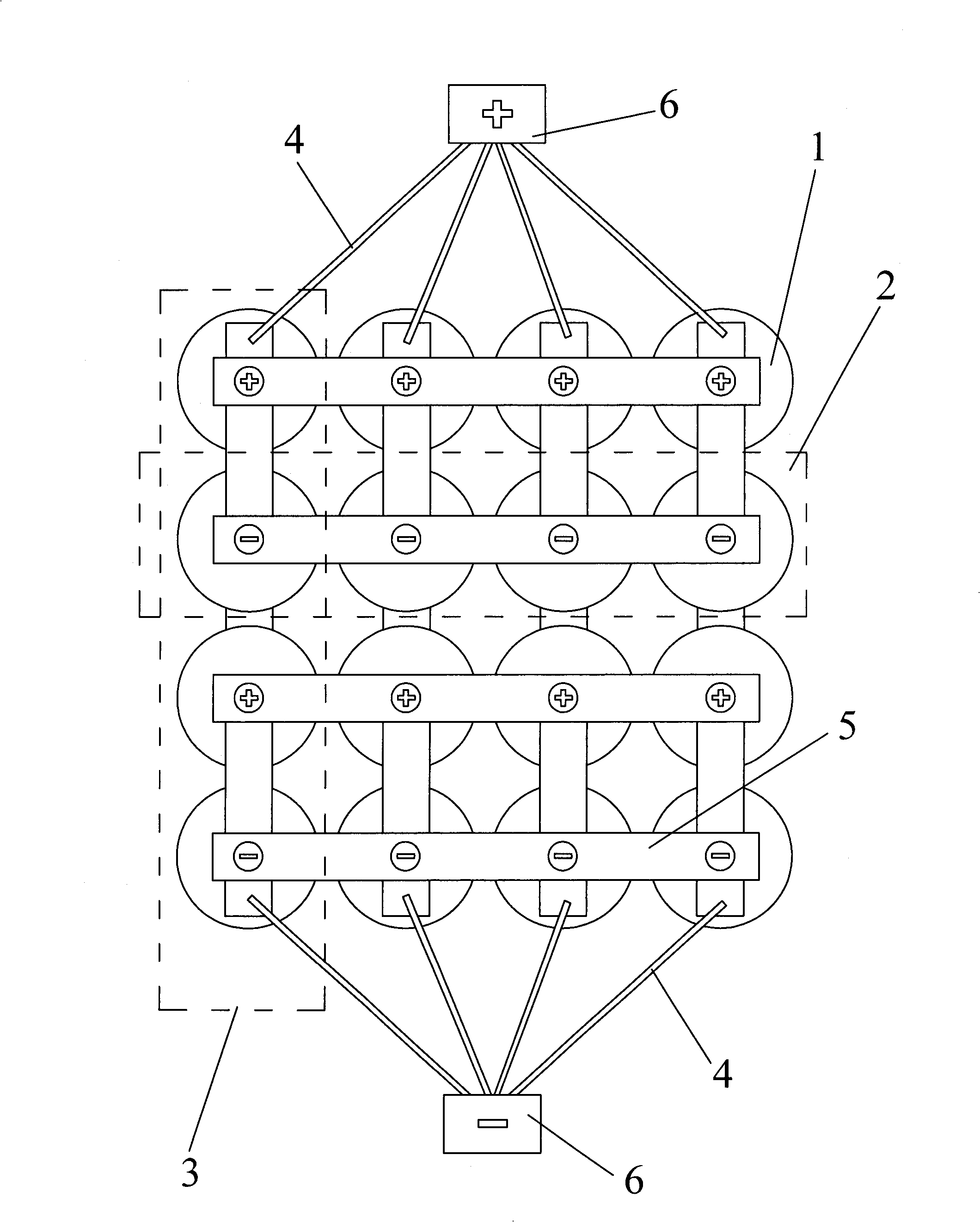
[0019] A battery pack, including several parallel branches 2 connected in parallel by battery cells 1 through busbars 5, and the corresponding battery cells 1 between the groups of parallel branches 2 are connected in series to form several series branches 3, such as figure 2 and image 3 As shown, each row of battery cells 1 forms a parallel branch 2, and each column of battery cells 1 forms a series branch 3, and each series branch 3 on the parallel battery pack 2 at the output end is connected to the output terminal through an independent conductor 4. 6 connections. The currents on the independent conductors between each series branch 3 and the output terminal 6 are similar or equal.
[0020] The independent conductors 4 are wires, and the resistances of the wires connected to the same output terminal 6 are similar or equal. For example, wires with the same resistivity×length÷cross-sectional area are used to make the load current of each single battery in the parallel ba...
specific Embodiment 2
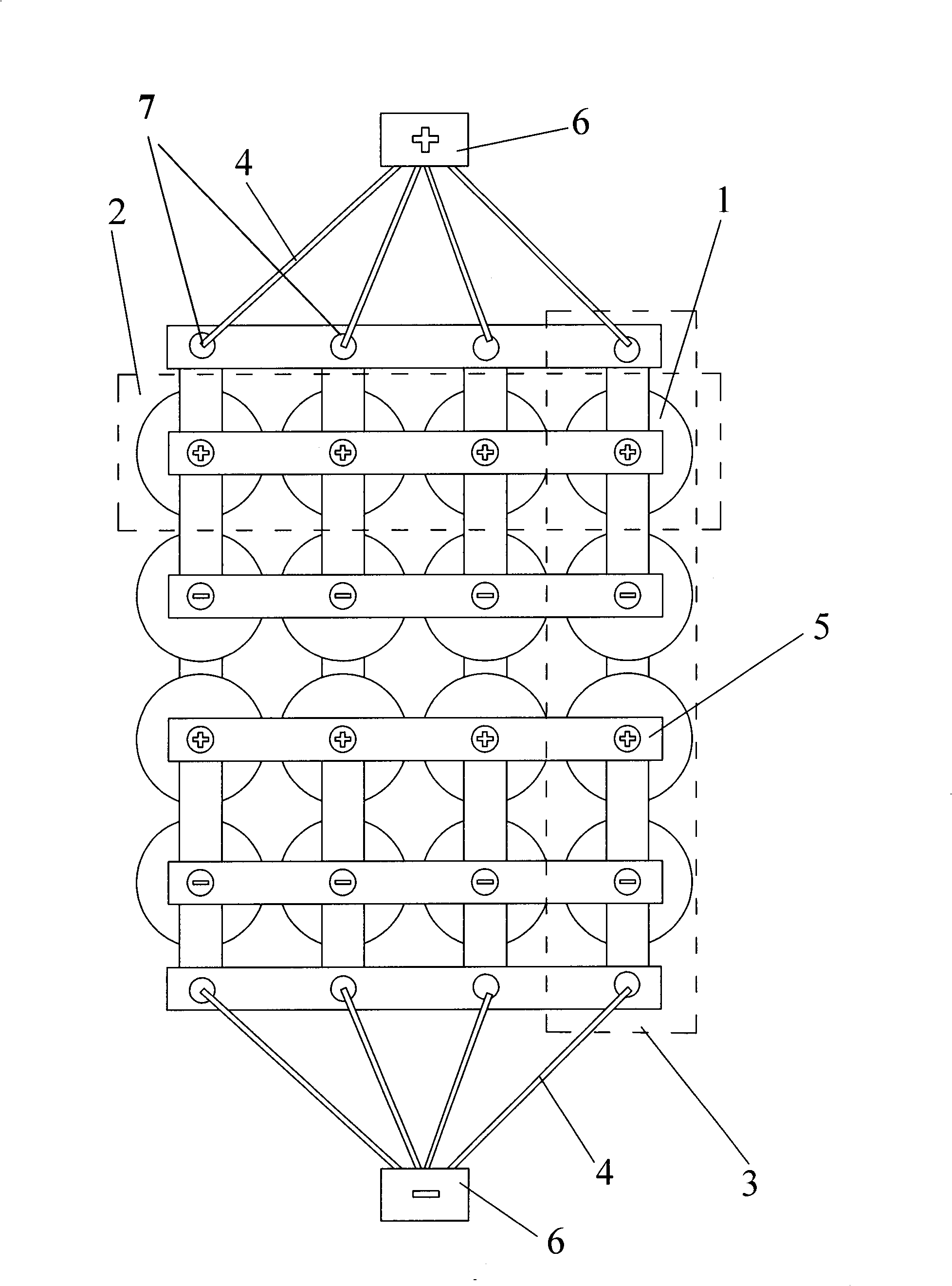
[0022] A battery pack, including several parallel branches 2 connected in parallel by battery cells 1 through busbars 5, and the corresponding battery cells 1 between the groups of parallel branches 2 are connected in series to form several series branches 3, such as figure 2 and image 3 As shown, each row of battery cells 1 forms a parallel branch 2, and each column of battery cells 1 forms a series branch 3, and each series branch 3 on the parallel battery pack 2 at the output end is connected to the output terminal through an independent conductor 4. 6 connections. The currents on the independent conductors between each series branch 3 and the output terminal 6 are similar or equal.
[0023] The independent conductors 4 are wires, and the resistances of the wires connected to the same output terminal 6 are similar or equal. For example, wires with the same resistivity×length÷cross-sectional area are used to make the load current of each single battery in the parallel ba...
specific Embodiment 3
[0025] A battery pack, including several parallel branches 2 connected in parallel by battery cells 1, and the corresponding battery cells 1 between the groups of parallel branches 2 are connected in series to form several series branches 3, such as Figure 4 As shown, each row of battery cells 1 forms a parallel branch 2 , and each row of battery cells 1 forms a series branch 3 , and each series branch 3 on the output parallel battery pack 2 is connected to a current collector 8 .
[0026] like Figure 5 As shown, the thickness direction of the current collector 8 increases or decreases stepwise.
[0027] like Image 6 As shown, the thickness direction of the current collector 8 increases or decreases linearly.
[0028] The battery pack is connected with an external circuit through a current collector output terminal 10 . The external circuit is connected to the thicker end of the current collector 8 .
[0029] The directions of the positive and negative battery pack outp...
PUM
 Abstract
Description
Claims
Application Information