Work machine with electrical and hydraulic service centers

A maintenance center and work machine technology, applied in the field of maintenance systems, which can solve the problems of parts located at high temperature, inconvenient maintenance, and a lot of time.

Inactive Publication Date: 2009-01-28
CATERPILLAR INC
View PDF0 Cites 16 Cited by
  • Summary
  • Abstract
  • Description
  • Claims
  • Application Information

AI Technical Summary

Problems solved by technology

In prior art work machines, these maintenance points are distributed throughout the machine and are difficult to identify and access, and it takes a lot of time to perform inspection and maintenance procedures
[0004] Those skilled in the art will also appreciate that it is sometimes inconvenient to perform maintenance on the various maintenance points of a work machine's hydraulic and electrical systems when the machine is hot
For example, some maintenance points in prior art work machines may be located near hotter parts such as the engine

Method used


Image

  • Work machine with electrical and hydraulic service centers
  • Work machine with electrical and hydraulic service centers
  • Work machine with electrical and hydraulic service centers

Examples


Embodiment Construction

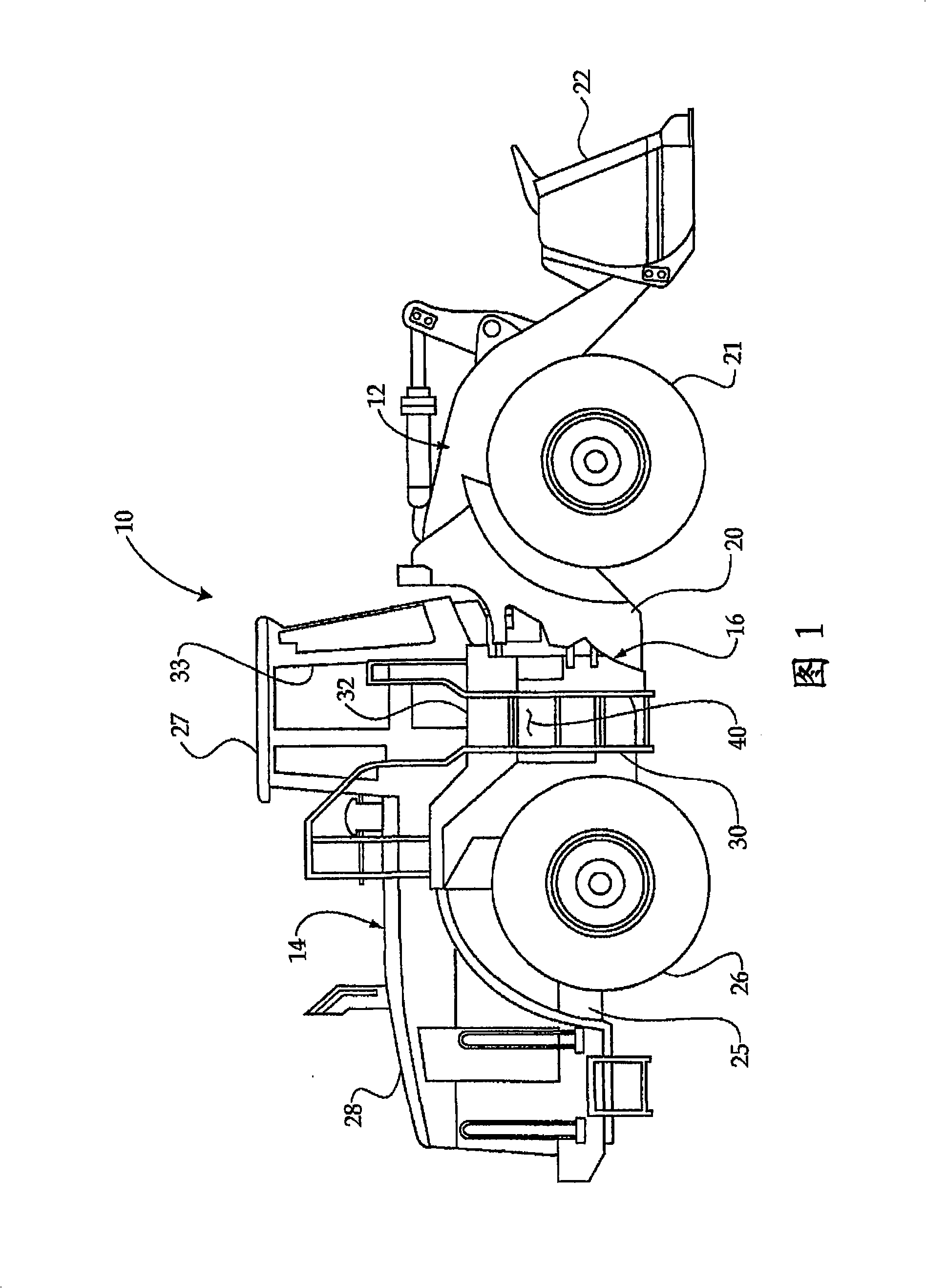
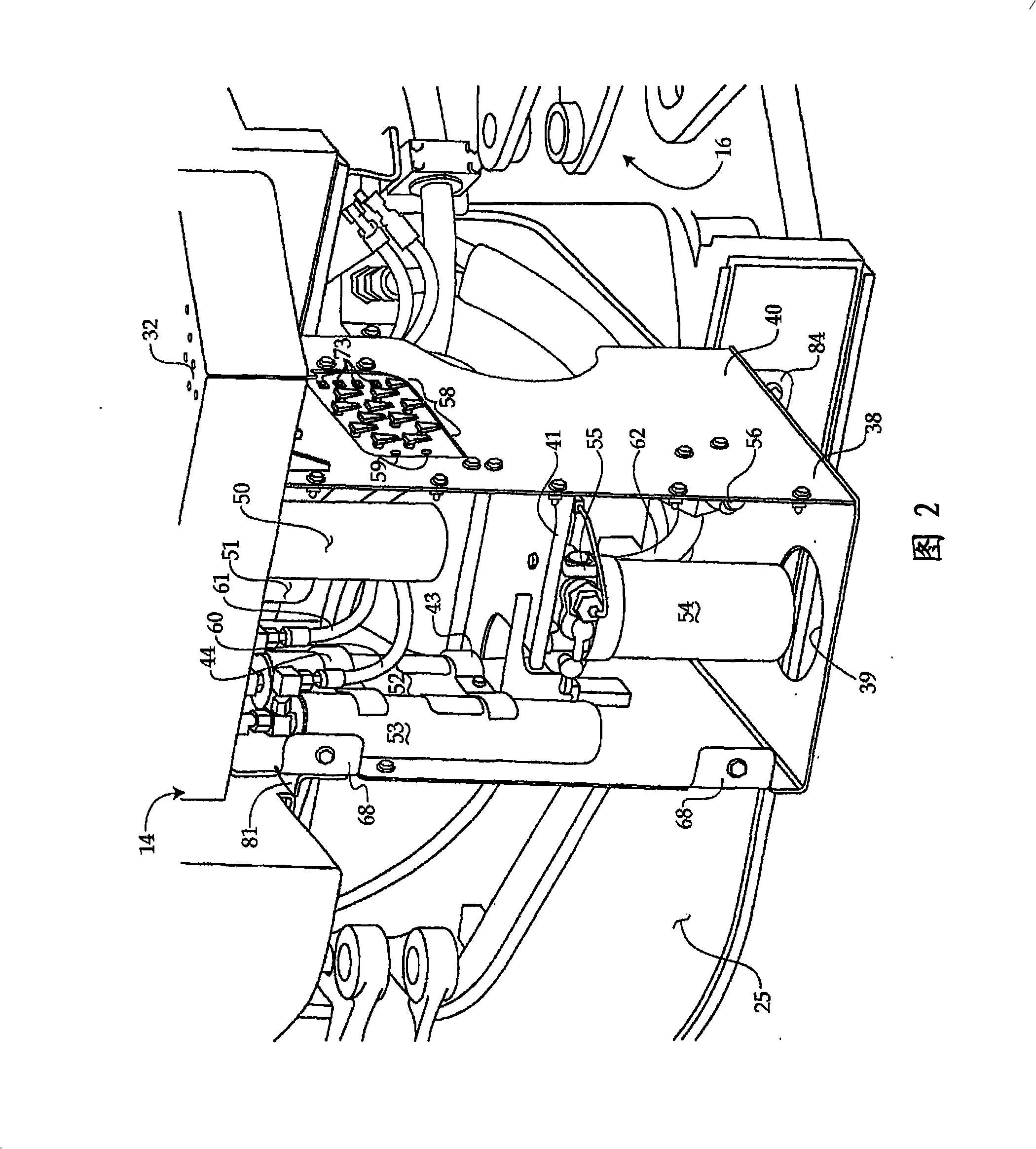
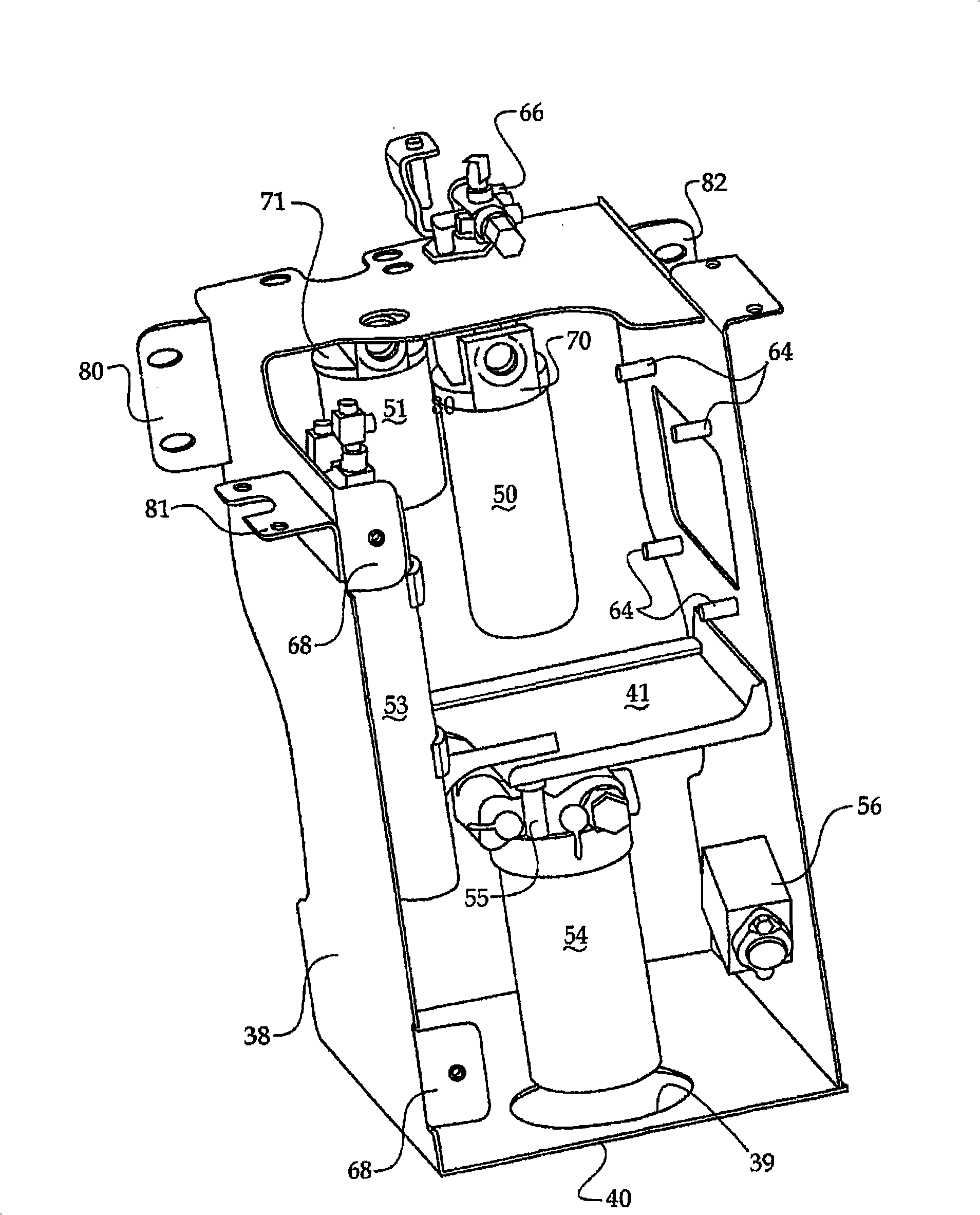
[0017] 1 to 5, the work machine 10 is shown as an articulated wheel loader with a chassis, which includes a front part 12 connected to a rear part 14 by a hinge 16. The hinge 16 allows the front frame 20 to pivot relative to the rear frame 25 about a vertical axis. The steering of the working machine 10 can be achieved in a conventional manner by a suitable actuator through a hinge 16. The front part 12 includes a front frame 20, a pair of front wheels 21 and a movable bucket 22. The rear part 14 includes a rear frame 25, a pair of rear wheels 26, a cab 27 and an engine 28. The operation room 27 can be reached from the right side through the step 30, the step 32 and the door 33 or the other step 130, 131, the step 132 and the left side door (not shown) on the left side (FIG. 5). The operator reaches the operating room or cab 27 upwards by climbing up the stairs 30 and standing on the stairs 32 on the right side. The door 33 can then be opened, and the operator enters the cab 27. Y...


PUM


Abstract

An articulated work machine (10), such as a wheel loader, includes many regularly serviced hydraulic points, such as a hydraulic fluid filter (50), a case drain filter (51), a transmission fluid filter (54) and brake accumulators (52, 53) that are grouped and mounted in a common service center subassembly (40), which may be preassembled and then later attached to the chassis when the machine (10) is being built. Likewise, an electrical service center subassembly (140) might include a battery box (144), relays and an emergency shutoff switch (150) that can be preassembled and attached to the machine chassis as a unit at the time that the work machine (10) is being built. The respective hydraulic and electrical service centers (40, 140) are attached to the work machine chassis underneath cab access steps (32, 132) on opposite sides of the machine (10). This strategy allows for a potential reduction in cost during the work machine (10) manufacture, and also better facilitates servicing of the hydraulic and / or electrical service points at an easily accessible and common location(s).

Description

Technical field [0001] The present invention generally relates to maintenance systems related to work machines, and in particular to grouping hydraulic and / or electrical maintenance points at a common maintenance center that is easily accessible on work machines such as wheel loaders. Background technique [0002] Work machines usually include many electrical and hydraulic systems that require periodic maintenance and / or monitoring. For example, a conventional work machine may include a hydraulic execution system including a pump and a hydraulic cylinder for operating an actuator related to the work machine. The hydraulic actuator system generally includes a case drain filter for trapping residue / debris leaving the pump and a hydraulic fluid filter for continuously trapping dirt, dust, and other particulate matter entering the hydraulic system. The internal combustion engine that powers the working machine usually includes a lubricating oil system with lubricating oil flowing thr...

Claims


Application Information

Patent Timeline
Patent Type & Authority Applications(China)
IPC IPC(8): E02F9/22E02F9/20E02F9/08B62D53/02B62D25/00B60R3/00B60R17/00
CPCY10T29/49826E02F9/2275E02F9/0833E02F9/0841
Inventor K·R·帕尔伯格B·恩德斯T·M·古茨维勒M·J·凯恩
Owner CATERPILLAR INC
Why Eureka
Try Eureka