
Electric compressor

A technology of electric compressors and electric motors, which is applied in the direction of electric components, machines/engines, liquid fuel engines, etc. It can solve the problems of reduced efficiency of compressor assembly operations, waiting time for insulating resin curing, and unusable sealed terminals, etc., to achieve The effect of high assembly work efficiency

Inactive Publication Date: 2009-01-28
SANDEN CORP
View PDF1 Cites 13 Cited by
  • Summary
  • Abstract
  • Description
  • Claims
  • Application Information

AI Technical Summary

Problems solved by technology

[0003] However, in such an electric compressor in which the insulating resin flows into the casing and the connection between the conductive pin of the sealed terminal and the socket is reinforced with the insulating resin, there is a waiting time and a compression time for the curing of the insulating resin flowing into the casing. Efficiency of machine assembly work decreased, sealed terminals could not be reused because they were reinforced with resin, etc.

Method used


Image

  • Electric compressor

Examples


Embodiment Construction

[0041] Preferred embodiments of the present invention will be described below with reference to the accompanying drawings.

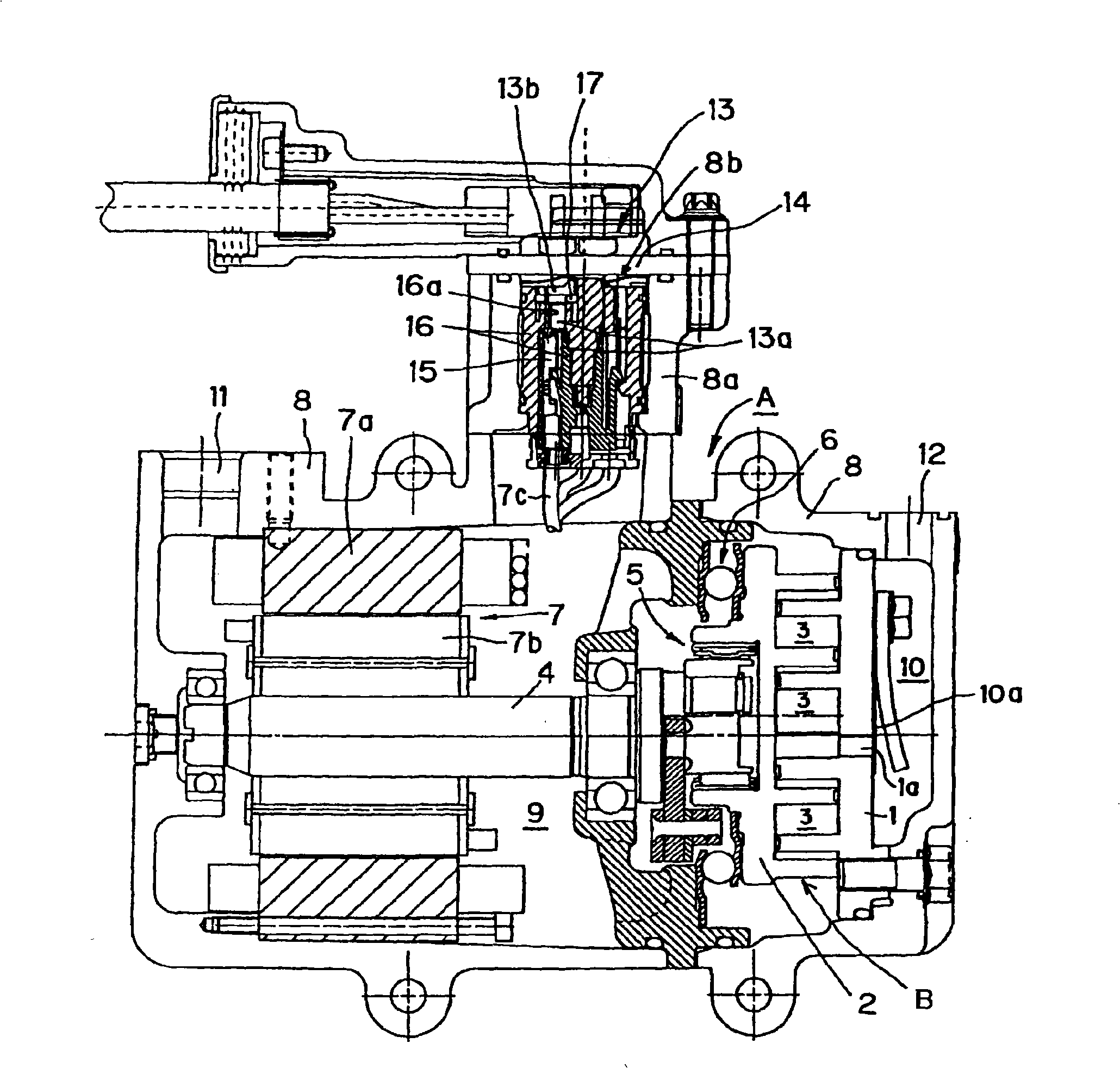
[0042] figure 1 Shown is an electric compressor according to one embodiment of the present invention, and a scroll electric compressor A is configured in this embodiment. The scroll compressor A includes: a fixed scroll 1 having a discharge hole 1a formed in the center thereof and having an end plate and a scroll body; and a movable scroll 2 having an end plate and a scroll body. The scroll body of the fixed scroll 1 and the scroll body of the movable scroll 2 are engaged with each other to form multiple pairs of working spaces 3 . Arranged are a main shaft 4 , a motion conversion mechanism 5 that converts the rotational motion of the main shaft 4 into a swivel motion and transmits it to the movable scroll 2 , and an anti-rotation mechanism 6 that prevents the movable scroll 2 from rotating. These fixed scroll 1 , movable scroll 2 , main shaft 4 , moti...


PUM


Abstract

An electric compressor having a compression mechanism, an electric motor for driving the compression mechanism, and a housing for receiving the compression mechanism and the electric motor. An opening formed in the housing is closed with a lid member to which a sealed terminal is attached, and an electroconductive pin of the sealed terminal is fitted in a socket connected to a lead wire of the electric motor. The socket is embedded in an insulative member, and the electroconductive pin of the sealed terminal is inserted in a hole formed in the insulative member and is fitted in the socket. An insulation section and the insulative member that surround the base of the electroconductive pin hold a ring member that is formed from an insulative elastic material and surrounds the electroconductive pin, and the portion held is sealed and insulated by elastic deformation of the ring member. Pouring and curing of resin for insulation, which have been necessary for a conventional structure, are not necessary, so that the electric compressor has high assembling efficiency and whose sealed terminal can be reused.

Description

technical field [0001] The present invention relates to an electric compressor, and more particularly to an improvement in the insulation structure of an electrical connection portion for supplying electric power to an electric motor. Background technique [0002] A compressor is disclosed in Patent Document 1 and the like. The compressor includes a compression mechanism, a motor for driving the compression mechanism, and a housing for accommodating the compression mechanism and the motor. opening, and insert the conductive pins of the sealed terminals into the sockets that connect to the ends of the motor leads. In the electric compressor disclosed in Patent Document 1, etc., in order to insulate the connecting portion between the conductive pin and the socket, usually after connecting both, an insulating resin is poured into the case, and the connecting portion is reinforced with the insulating resin. . [0003] However, in such an electric compressor in which the insula...

Claims


Application Information

Patent Timeline
Patent Type & Authority Applications(China)
IPC IPC(8): F04B39/00F04C18/02F04C29/00
CPCH02K5/225H01R13/521F04B35/04H02K7/14H02K5/12F04C2240/803F04C18/0215F04B39/12
Inventor 根岸泰隆松岛昌宏
Owner SANDEN CORP
Learn More