High resolution autostereoscopic display apparatus with interlaced image

A technology for autostereoscopic display and equipment, which is applied in image communication, stereoscopic systems, electrical components, etc., and can solve the problems of expensive light deflection units and high light loss

Inactive Publication Date: 2009-01-28
SAMSUNG ELECTRONICS CO LTD
View PDF2 Cites 18 Cited by
  • Summary
  • Abstract
  • Description
  • Claims
  • Application Information

AI Technical Summary

Problems solved by technology

However, there is a problem that the light deflecting unit formed of ferroelectric li

Method used


Image

  • High resolution autostereoscopic display apparatus with interlaced image
  • High resolution autostereoscopic display apparatus with interlaced image
  • High resolution autostereoscopic display apparatus with interlaced image

Examples


Embodiment Construction

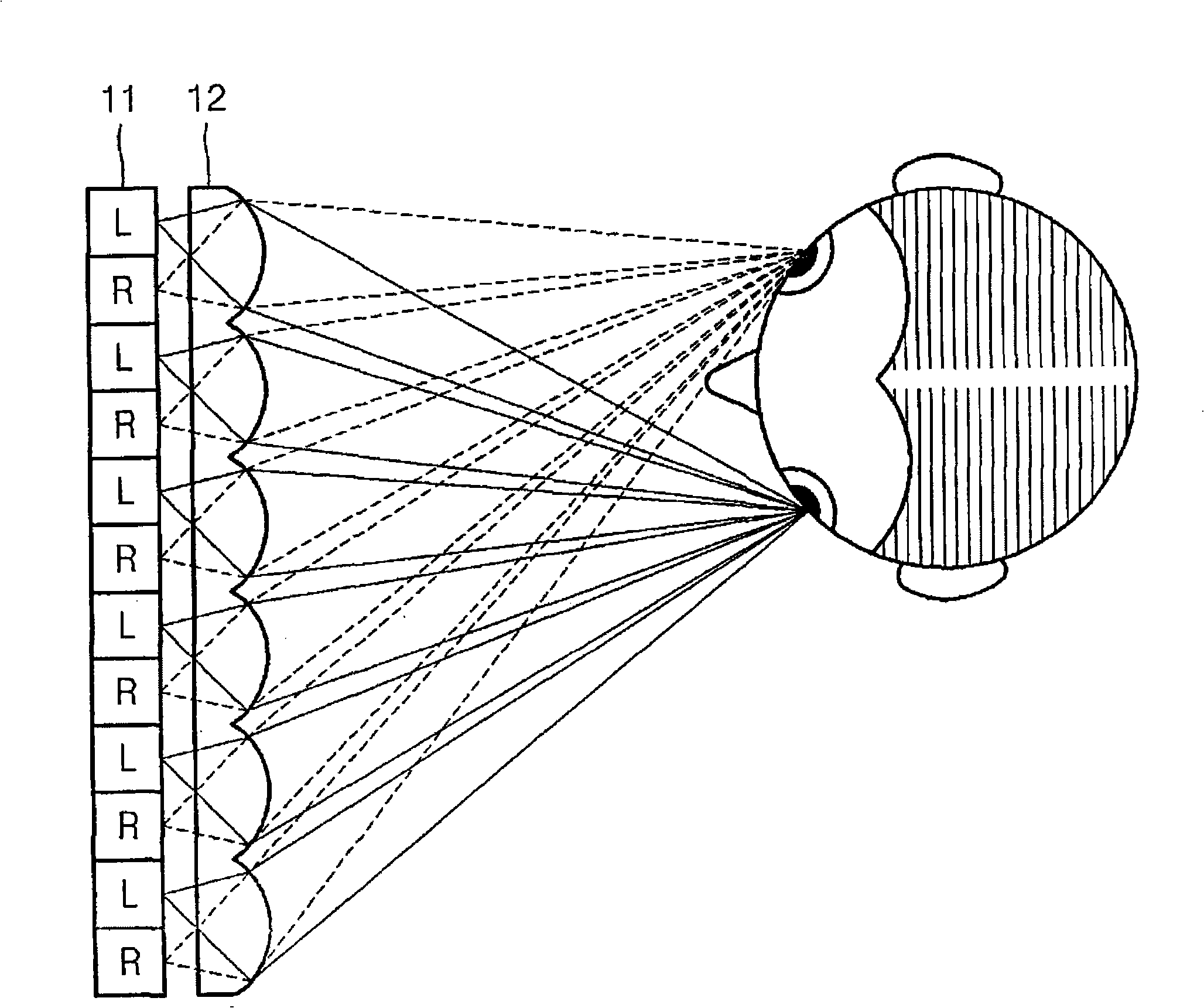
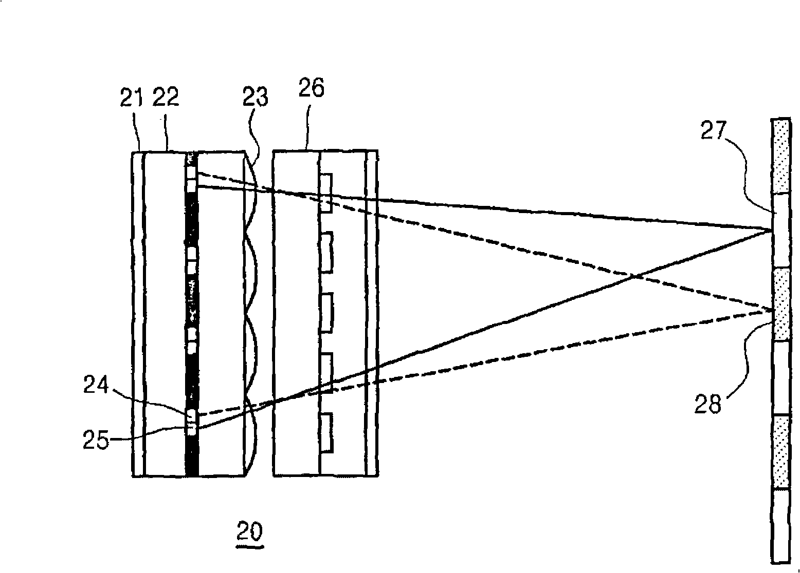
[0076] Figure 5 is an exploded perspective view schematically showing the structure of a high-resolution autostereoscopic display device 30 according to an exemplary embodiment of the present invention. refer to Figure 5 , the high-resolution autostereoscopic display device 30 in the current embodiment includes: a division type (division type) backlight unit 31; a polarizing plate 32 that only transmits light with a specific polarization direction incident from the backlight unit 31; a spatial light modulator 33 , change the polarization direction of the incident light according to electric control; the first birefringent element array 34, in the first birefringent element array 34, a plurality of first vertical birefringent elements 34a and second vertical birefringent elements 34a that change the polarization direction of the incident light The birefringent elements 34b are alternately arranged along the horizontal direction; the particle lens sheet 35 separates the incid...


PUM


Abstract

An autostereoscopic display apparatus includes a backlight unit, a polarizing plate disposed in front of the backlight unit; a display panel displaying a left eye image and a right eye image by interlacing pixel lines of the left and right eye images alternately and sequentially; a lenticular lens sheet, disposed between the polarizing plate and the display panel, separating light emitted from the backlight unit into a left eye zone and a right eye zone; and a polarization switch controlling a polarization direction of light proceeding towards the left eye viewing zone so that light is incident on pixel lines of the display panel displaying the left eye image and a polarization direction of light proceeding towards the right eye viewing zone so that light is incident on pixel lines of the display panel displaying the right eye image, in synchronization with a vertical scanning time of the display panel.

Description

technical field [0001] Apparatus consistent with the present invention relates to a high-resolution autostereoscopic display, and more particularly to a high-resolution autostereoscopic display with no reduction in resolution and no crosstalk when displaying images in an interlaced method. Stereoscopic display device. Background technique [0002] The autostereoscopic display device is for displaying an image for the left eye and an image for the right eye exhibiting binocular parallax to the left and right eyes of the viewer, respectively. A viewer can recognize a left-eye image and a right-eye image provided by the autostereoscopic display device through the retinas of both eyes, thereby seeing a 3D image. Autostereoscopic display devices include devices using a parallax barrier method and devices using a lenticular method. [0003] According to the parallax barrier method, images to be seen by left and right eyes are alternately displayed in a vertical mode, and the dis...

Claims


Application Information

Patent Timeline
IPC IPC(8): H04N13/04
Inventor 萨古·切斯塔金大式郑吉洙
Owner SAMSUNG ELECTRONICS CO LTD
Why Eureka
Try Eureka