Column crane special for movable arm type group tower

A technology of tower crane and tower grouping, which is applied to cranes and other directions, can solve the problems of reduced construction efficiency, low safety factor, low construction efficiency, etc., and achieve the effects of improving construction efficiency, high safety factor and low construction cost.

Active Publication Date: 2009-02-04
CHINA ELECTRIC POWER RES INST
View PDF0 Cites 15 Cited by
  • Summary
  • Abstract
  • Description
  • Claims
  • Application Information

AI Technical Summary

Problems solved by technology

[0002] At present, the jib of the tower crane commonly used in the construction of domestic transmission line iron towers can only reach an upward angle of 85° in the vertical plane and is equipped with a balance arm. The balance arm cannot pass through the window at the top of the tower, so it is complicated and difficult to dismantle the tower crane; in addition, the lifting mechanism of a conventional tower crane is usually located on the balance arm of the crane or on the ground, and placing the lifting mechanism on the ground will not only increase the The amount of steel wire rope will also make the lifting work journey too long, thereby reducing the construction efficiency. The driver's cab is placed on the upper part of the crane, and the working status of the crane is monitored by the driver's eyesight, so the safety factor is not high in ensuring the driver's personal safety.
Therefore, when using this tower crane for tower construction, the construction is complicated, the safety factor is not high, the construction efficiency is low, and the cost is high.

Method used


Image

  • Column crane special for movable arm type group tower
  • Column crane special for movable arm type group tower
  • Column crane special for movable arm type group tower

Examples


Embodiment Construction

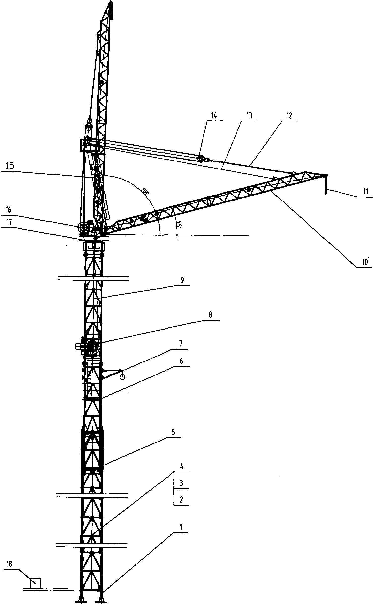
[0023] See figure 1 Shown: A special tower crane for luffing jib tower assembly. The boom can be raised up to 89° in the vertical plane. It includes fixed feet 1, standard section 2, rest platform 3, standard channel 4, and lifting device 5. Inner tower section for lifting 6. Hanger for demolition of tower 7. Lifting mechanism 8. Inner tower section for lifting 9. Boom assembly 10, hook pulley group 11, luffing rope 12, safety rope 13. The luffing pulley group 14, the tower top strut 15, the luffing mechanism 16, the turning assembly 17, and the driver's cab 18. The crane has no balance boom.

[0024] The upper end of the standard section is connected to the inner tower section for jacking through the existing connecting mechanism; the jacking device is installed at the lower end of the inner tower section for jacking, which is a prior art, the upper end of the inner tower section for jacking The inner tower section for lifting is fixedly connected by the existing fishplate and c...


PUM


Abstract

The invention provides a special tower typed crane with a movable arm group tower, wherein, the tower body is connected by a fixed support arm 1, a standard section 2, and a jacking inner tower section 6; a hoisting inner tower section 9 is arranged on the jacking inner tower section; a rotary assembly 17 is arranged on the hoisting inner tower section 9 to articulate a boom 10, besides, a derricking mechanism 16 is also arranged on the hoisting inner tower section 9; wherein, a derricking cord 12 is connected between a windlass 19 and the boom to ensure that the boom can rotate in a scope of 15-89 degrees on a vertical plane; a hoisting mechanism 8 is arranged on the hoisting inner tower section; wherein, a hoisting cable is connected between the windlass and a hook pulley block 11 on the boom. When the crane is needed to be dismantled in the process of working in a form of inner attachment, the boom is boosted for an angle of 89 degree through the derricking mechanism to ensure the passing of the boom through a window at the top of the tower and ensure automatic falling from the middle of the iron tower; the hoisting mechanism 8 is positioned on the tower body, thus shortening the hoisting working trip to improve the construction efficiency; a hanger for dismantling the tower can also be arranged on the tower body to dismantle the crane conveniently; the crane has a simple and convenient construction, low construction cost and extensive application scope.

Description

Technical field [0001] The invention relates to the technical field of power transmission line construction. It is a tower crane with a boom that can rotate upwards by 89° in a vertical plane without a balance arm and a lifting mechanism on the tower body. It is particularly suitable for the construction of power transmission line towers . Background technique [0002] At present, the tower crane boom commonly used in the construction of transmission line towers in China can only reach an upward angle of 85° in the vertical plane and is equipped with a balance arm. During the construction of the internally attached tower, due to the boom, The balance arm cannot pass through the uppermost window of the iron tower, so it is complicated and difficult to dismantle the tower crane; in addition, the lifting mechanism of the conventional tower crane is usually located on the balance arm of the crane or on the ground, and placing the lifting mechanism on the ground will not only increase...

Claims


Application Information

Patent Timeline
Patent Type & Authority Applications(China)
IPC IPC(8): B66C23/06B66C23/62B66C23/18B66C23/88
Inventor 缪谦江明苏杰谢毅娜
Owner CHINA ELECTRIC POWER RES INST
Why Eureka
Try Eureka