
Deep-drawing processing device

A technology of deep processing and installation platform, which is applied in the field of retrograde mechanism improvement, can solve the problems of taking a long time, costing more trouble, and taking a long time to troubleshoot, so as to reduce the replacement operation, simplify the structure, and reduce the replacement frequency. Effect

Active Publication Date: 2009-02-11
NIHON SPINDLE MFG CO LTD
View PDF1 Cites 3 Cited by
  • Summary
  • Abstract
  • Description
  • Claims
  • Application Information

AI Technical Summary

Problems solved by technology

[0017] However, this reversing mechanism 50 is configured by dividing the supporting member 17 into a lower moving member 51 and an upper moving member 56, so that the moving direction of the guide pin 51a arranged on the lower moving member 51 is changed from the direction engraved on the lower moving member 51 to the lower moving member 51. The upper rack 51b passes through the gear 52, the intermediate gear 53, and the drive gear 54 to reversely transmit to the rack 56a engraved on the upper moving member 56. Due to the complex structure, in order to remove the guide pin 51a that needs to be replaced regularly, Even the main shaft housing 11 must be removed, and a crane must be used to remove the main mounting table 14 which is a heavy object, and there is a problem that it takes a lot of trouble and takes a long time to do the work.
In addition, since three gears are arranged inside and racks are arranged at two places, there is a high possibility of cracks or damage to the teeth, and the replacement in case of damage is related to the work of replacing the guide pins. than, there is a problem that it takes more trouble and takes a long time

Method used


Image

  • Deep-drawing processing device
  • Deep-drawing processing device
  • Deep-drawing processing device

Examples


Embodiment 1

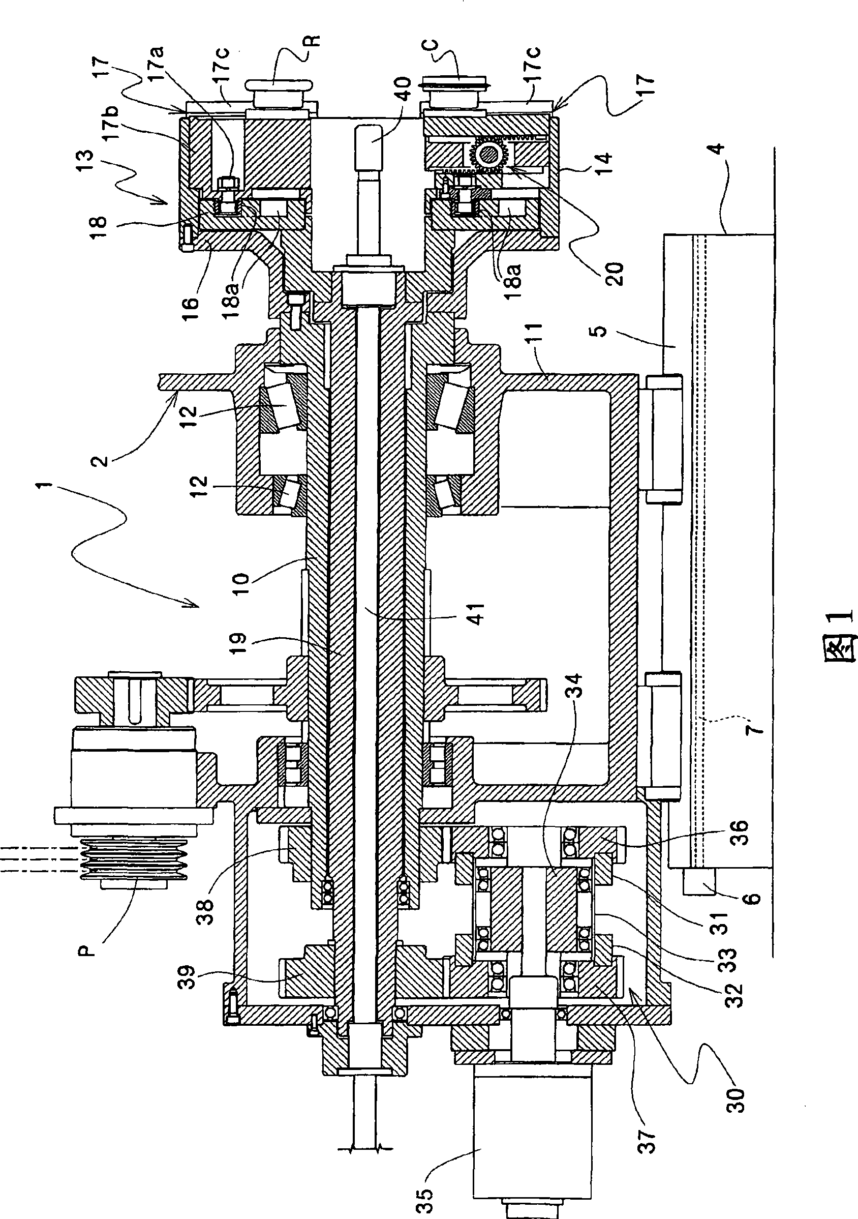
[0022] 1 to 7 show an embodiment of the drawing apparatus of the present invention.

[0023] This drawing processing device 1 is the same as the conventional example. At the front end of the main shaft 10, there is a roll mounting table 13 that supports the drawing roll R and the cutting roll C so as to be slidable in the radial direction. The front end of the camshaft 19 has a cam plate 18 that moves the above-mentioned drawing roller in the radial direction. After drawing the tip of the tube, the cutting roll C cuts off the remaining portion of the tip of the tube to be processed which has been reduced in diameter.

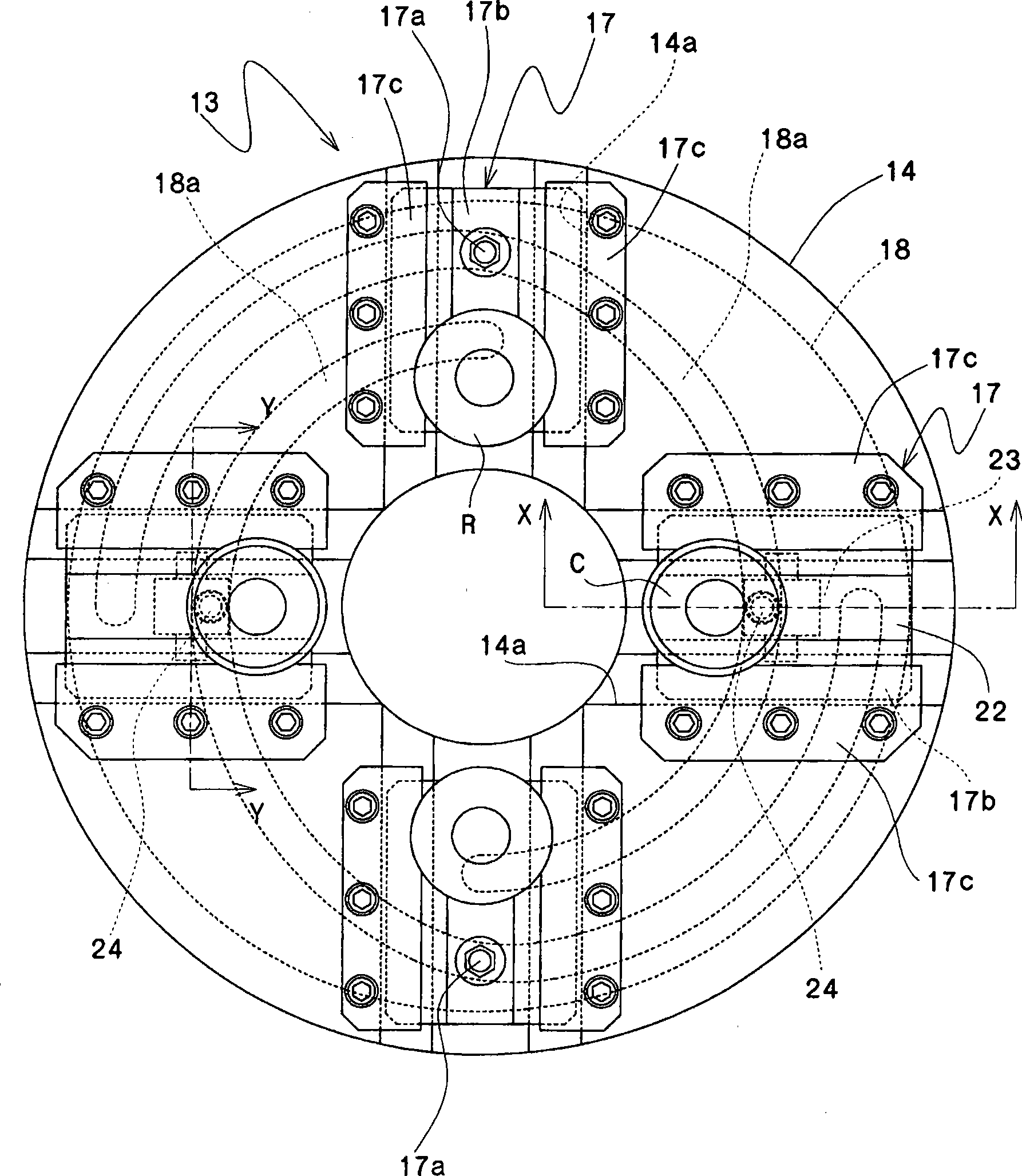
[0024] The number of arrangement of the drawing roll R and the cutting roll C is not particularly limited. In this embodiment, such as figure 2 As shown, an example in which two drawing rolls R and a cutting roll C are respectively arranged at opposing positions is shown.

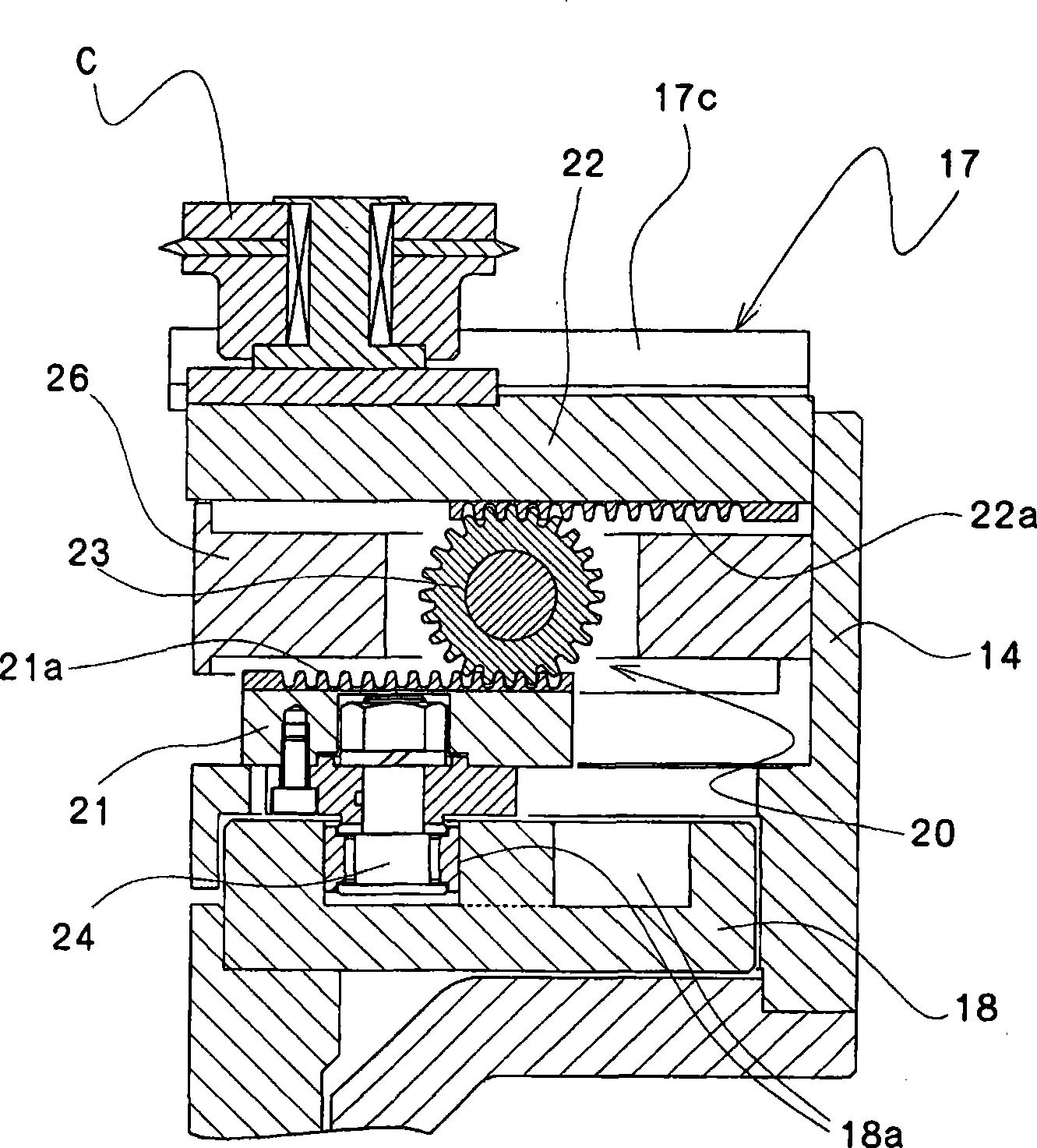
[0025] Then, the guide pins 17a and 24 of the drawing roll R on the upper side of the ...

Embodiment 2

[0037] Figure 8~ Figure 14 Another example using the drawing processing apparatus of this invention is shown.

[0038] In this drawing processing apparatus 1A, when drawing a cylindrical blank with a thin wall or a cylindrical blank with a large diameter, the processing part (tip portion) of the cylindrical blank does not move until it moves along the mandrel. It is constructed in such a way that it deforms abnormally inside due to the pressing force of the drawing roll, and the front end of the main shaft 10 has a roll mounting table 13 that can support the drawing roll R, and at the same time, the drawing roll R is moved in the radial direction. In the drawing processing device for shrinking the front end of the fixed cylindrical blank, the roll mounting table 13 is provided with a roller that is located inside the cylindrical blank and moves in the radial direction of the spindle 10 during the shrinking process. Backup roller 60.

[0039] The number of arrangement of the...

Embodiment 3

[0055] Figure 15~ Figure 20 Another example using the drawing processing apparatus of this invention is shown.

[0056] This drawing processing device 1B can perform the process of removing the burr inside the cut surface generated when the unnecessary part of the end portion is cut by the cutting roll in a continuous process with the drawing process and the cutting process. A drawing processing device that supports the roll mounting table 13 of the drawing roll R movably in the radial direction, and simultaneously moves the drawing roll R in the radial direction to shrink the front end of a fixedly installed cylindrical billet A chamfering tool 70 that moves in the radial direction of the main shaft 10 to finish the end of the formed blank is disposed on the roller mount 13 .

In addition, in the case of a thin-walled or large-diameter cylindrical billet to be processed, on the roller mounting table 13, such as Figure 16 As shown, at a position facing the chamfering tool ...


PUM


Abstract

Deep drawing processing device is able to simply replace the guide pin configured with supporting member of recessive mechanism. Front end of the main shaft (10) is provided with a deep drawing roller installation stage (13) slidably supporting a deep drawing roller (R) and a cutting roller (C) at the radial direction; the front end of cam shaft (19) concentrically inserted with the main shaft isprovided with a cam plate (18) of turbulent groove (18a) embedded from the guide pin (17a, 24) protruding supporting member (17) supporting the supporting deep drawing roller and cutting roller; any one of the deep drawing roller and cutting roller reverses from the moving direction of the guide pin to the moving direction of the roller by the conversing mechanism (20); the deformation part (alpha, gamma) of the other turbulent groove moves the two rollers (R, C) at the radial direction. The inversing mechanism is composed of a rack (21a) scored on upper surface of a guide slipper block (21) configuring the guide pin (24), a rack (22a) scored on bottom of roller slipper block (22) configuring the deep drawing roller or the cutting roller and a small gear (23) freely arranged between two racks.

Description

technical field [0001] The present invention relates to a deep-drawing device, and in particular to an improvement of a retrograde mechanism for making two kinds of rollers move in opposite directions by means of a spiral groove engraved on a cam plate. Background technique [0002] Conventionally, as a drawing processing device for drawing a cylindrical member at the tip of a pipe, the present applicants have previously proposed a drawing roll mounting table that is slidably supported in the radial direction and mounted on the tip of a rotating main shaft, and that A drawing processing apparatus for performing drawing processing on the front end of the pipe to be processed thus fixed (for example, refer to Patent Document 1). [0003] Figure 21~ Figure 27 An example of a conventional drawing processing device is shown. This deep-drawing processing device 3 has a main shaft mechanism 2 and a support mechanism (not shown) that supports the pipe to be processed facing the m...

Claims


Application Information

Patent Timeline
IPC IPC(8): B21D22/14B21D41/04
Inventor 小岛宏畠直人
Owner NIHON SPINDLE MFG CO LTD
Learn More