Check patentability & draft patents in minutes with Patsnap Eureka AI!

Method for forming orifice in a secondary shell of pressurized water reactor steam generator

A technology of steam generator and pressurized water reactor, which is applied in steam generation method, steam generation method using heat carrier, steam generation, etc., can solve difficult problems, can not be used to inspect or clean steam generator tube bundles, limited inspection area, etc. question

Inactive Publication Date: 2009-02-11
FRAMATOME ANP +1
View PDF0 Cites 6 Cited by
  • Summary
  • Abstract
  • Description
  • Claims
  • Application Information

AI Technical Summary

Problems solved by technology

The use of this method is limited because probes or cameras with extremely small diameters have to be used, and because the inspection area is limited due to the presence of anti-vibration rods in the upper part of the Inspection in the generator bundle
[0023] Therefore, these known visual inspection or cleaning methods and devices cannot be used to inspect or clean the upper part of the steam generator tube bundle, unless the steam generator has a tube support plate with openings perpendicular to the tube gallery or water hole align
Therefore, this method and apparatus cannot be used for a large number of steam generators of various types that do not have these special design features in terms of tube support plates
[0024] In addition, in order to be able to reach the space between the tubes above the individual tube support plates distributed over the height of the tube bundle, these known inspection or cleaning devices change the direction of the path three or four times and have to follow the Move vertically towards the upper part of the evaporator tube bundle
All of these constraints make the movement and operation of these interventional devices within the steam generator bundle complex and tricky

Method used


Image

  • Method for forming orifice in a secondary shell of pressurized water reactor steam generator
  • Method for forming orifice in a secondary shell of pressurized water reactor steam generator
  • Method for forming orifice in a secondary shell of pressurized water reactor steam generator

Examples


Embodiment Construction

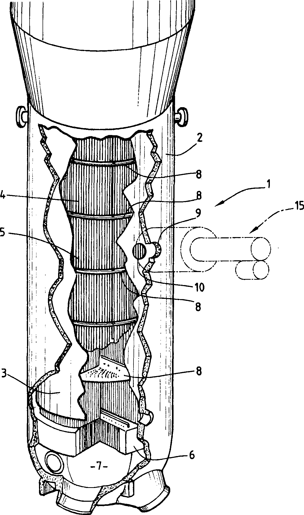
[0047] figure 1 The lower part of the pressurized water reactor steam generator, generally designated by reference numeral 1, is shown.

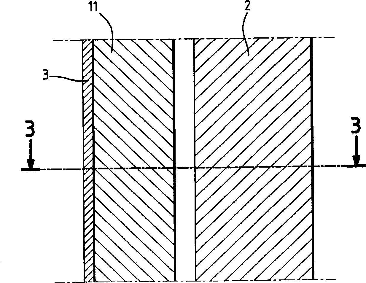
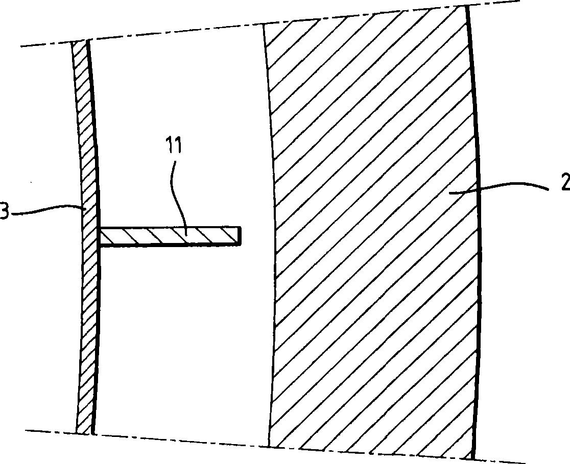
[0048] The steam generator 1 comprises, in a conventional manner, an essentially cylindrical pressure boundary 2 , inside which is coaxially positioned a tube bundle envelope 3 containing the tube bundles 4 of the steam generator 1 .

[0049] The tube bundle 4 consists of a large number of tubes 5 bent into a U-shape, each tube 5 comprising two straight branches which at their ends are connected to a tube sheet fixed to the lower part of the pressure boundary 2 of the steam generator 1 6 is engaged and fixed therein. The pressure boundary 2 is connected to a hemispherical end defining a tank 7 in two parts.

[0050] Inside the tube bundle envelope 3, at continuous positions along the height of the tube bundle, tube support plates 8 are fixed, and the tube support plates 8 are used to fix the branches of the tubes 5 in the bundle 4 in place...


PUM


Abstract

A method for forming orifice in second shell of vapor generator of pressurized water reactor; the method comprises the following steps: ensuring the vapor generator (1) is filled with water; if necessary, filling the water to full; utilizing machine drilling tool (15) to penetrate partial thickness of the pressure boundary (2) to form a prefabricated dead hole (22); decreasing the water level in the vapor generator (1) to the upper part of the prefabricated dead hole (22); utilizing spark machining apparatus to finish the operation of forming the orifice (9) penetration in the pressure boundary (2); and still utilizing the spark machining apparatus to form the orifice (10) in the tube bundle encapsulation piece (3).

Description

technical field [0001] The present invention relates to a method for forming an orifice in a secondary casing of a pressurized water reactor steam generator. Background technique [0002] A steam generator for generating steam by means of heat supplied by the cooling water of a pressurized water reactor comprises a generally cylindrical casing, known as the pressure boundary, positioned with its axis vertical and enclosing the The internal structure specifically includes: bundled tubes for heat exchange between the primary fluid and feed water, wherein the primary fluid is composed of pressurized cooling water for cooling the atomic reactor and the bundled tubes The internal flow of pressurized cooling water; while the feed water contacts the outer surfaces of the bundled tubes in the secondary section of the steam generator. [0003] The steam generator tube bundle consists of a large number of heat exchange tubes bent in a U shape, each heat exchange tube having two strai...

Claims


Application Information

Patent Timeline
Patent Type & Authority Applications(China)
IPC IPC(8): B23H9/14F22B1/16
CPCF22B1/025F22B37/002Y10T29/49352
Inventor O·泰利耶J-C·费拉
Owner FRAMATOME ANP
Features
  • R&D
  • Intellectual Property
  • Life Sciences
  • Materials
  • Tech Scout
  • Unparalleled Data Quality
  • Higher Quality Content
  • 60% Fewer Hallucinations
Learn More