Processing technique of split type speed differentiator shell

A differential case and processing technology, which is applied to metal processing equipment, metal processing machinery parts, manufacturing tools, etc., can solve the problem of high rework assembly rate, difficulty in assembling the end face of driven gear and stop beating, and ensure the design requirements and production efficiency Low and other problems, achieve the effect of reducing rear axle noise, high production efficiency, and quality improvement

Inactive Publication Date: 2009-02-11
JIANGXI JIANGLING CHASSIS CO LTD
View PDF0 Cites 28 Cited by
  • Summary
  • Abstract
  • Description
  • Claims
  • Application Information

AI Technical Summary

Problems solved by technology

[0002] At present, the finishing of the outer circle surface of each section of the domestic split differential housing assembly bearing is generally done by ordinary grinding machine or CNC grinding machine. The disadvantages are mainly low production efficiency, and it is difficult to ensure the design of the assembly driven gear end face and seam runout. It is required that the runout of the flange end face and the outer circle of the spigot reach 0.04~0.06 for the two journals, and the rework assembly rate must be high. In order to ensure the runout of the flange surface of the split differential case is lower than 0.06 and meet the requirements for assembling passive gears, the reduced Bridge gear noise, and can be mass-produced, only to seek better and faster processing technology for the outer circle and end face of each section of the split differential case

Method used


Image

  • Processing technique of split type speed differentiator shell
  • Processing technique of split type speed differentiator shell

Examples


Embodiment 1

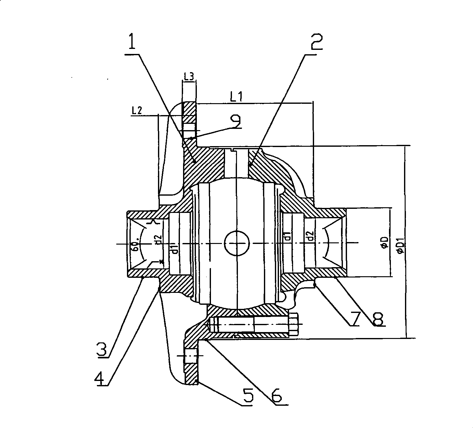
[0011] Example 1: Taking the processing of the Transit type split differential case as an example, it is to process the two journals ΦD for matching the differential case and the bearing, and the outer circular surface and end face of ΦD1 for matching the driven gear; the outer surface of the assembled bearing is rough The surface roughness value of the assembly driven gear is required to be less than Ra1.6; the surface roughness value of the assembly driven gear is less than Ra1.6; the outer circle runout of the flange facing the two journals is guaranteed to be less than 0.06.

[0012] The clamping and positioning of the Transit differential housing is as follows: the spindle end of the machine tool is matched with the positioning mandrel and the differential housing hole, with a gap of 0.02 to 0.05, and the axial positioning is performed by the small end face of the left housing of the differential; or the self-centering tensioning fixture is used , One end of the tailstock ...


PUM


Abstract

The invention relates to a processing technique of a split type differential case, which belongs to the technical field of mechanical working. The inner cavities of a left differential case 1 and a right differential case 2 are fine-processed according to the technical requirement, and the inner cavities comprise spherical surfaces, half axle gear holes, half axle via holes, joint surfaces of the differential cases, and assembling rabbets of the left differential case and the right differential case; a surplus length of 0.4-0.5 is reserved on each excircle, a surplus length of 0.3 is reserved on the corresponding end surfaces, the left differential case 1 and the right differential case 2 are assembled, ten holes are drilled and bored, then a numerical control lathe is utilized for finish turning to each excircle and end surface of the differential case, the roughness value Ra of the excircle surface of the assembling bearing is smaller than 1.6, the roughness value Ra of the excircle surface and the end surface of the rabbet on the flange surface is smaller than 3.2, and the jump of the flange surface relative to the two axle necks is smaller than 0.06. The processing technique has the advantages that the split type differential case is processed through turning rather than grinding, the production benefit is high, the working accuracy can achieve the design requirement, the quality is obviously improved than the separated processing, the noise of the rear axle is favorable to be reduced, therefore, the requirements of the users can be met.

Description

technical field [0001] The invention belongs to the field of mechanical processing technology, and relates to a processing technology of a split differential case. Background technique [0002] At present, the finishing of the outer circle surface of each section of the domestic split differential housing assembly bearing is generally done by ordinary grinding machine or CNC grinding machine. The disadvantages are mainly low production efficiency, and it is difficult to ensure the design of the assembly driven gear end face and seam runout. It is required that the runout of the flange end face and the outer circle of the spigot reach 0.04~0.06 for the two journals, and the rework assembly rate must be high. In order to ensure the runout of the flange surface of the split differential case is lower than 0.06 and meet the requirements for assembling passive gears, the reduced The axle gears are noisy and can be mass-produced. Only better and faster processing techniques for th...

Claims


Application Information

Patent Timeline
Patent Type & Authority Applications(China)
IPC IPC(8): B23P15/00B23B7/12B23Q3/12
Inventor 胡义华敖辉光黄国安吴北光
Owner JIANGXI JIANGLING CHASSIS CO LTD
Why Eureka
Try Eureka