Pyrolysis method and device of low speed bed

A low-speed, pyrolysis technology, applied in the field of pyrolysis, which can solve the problems of difficult heat disposal and difficult hot ash distribution.

Active Publication Date: 2009-02-11
INST OF ENGINEERING THERMOPHYSICS - CHINESE ACAD OF SCI
View PDF0 Cites 16 Cited by
  • Summary
  • Abstract
  • Description
  • Claims
  • Application Information

AI Technical Summary

Problems solved by technology

The shunting of high-temperature circulating ash is to use mechanical or pneumatic methods to send part of it into the pyrolysis chamber as a heat source for pyrolysis. The more ash that enters the pyrolysis chamber, the higher the temperature of the pyrolysis chamber, but the thermal ash Th

Method used


Image

  • Pyrolysis method and device of low speed bed
  • Pyrolysis method and device of low speed bed
  • Pyrolysis method and device of low speed bed

Examples


Embodiment 1

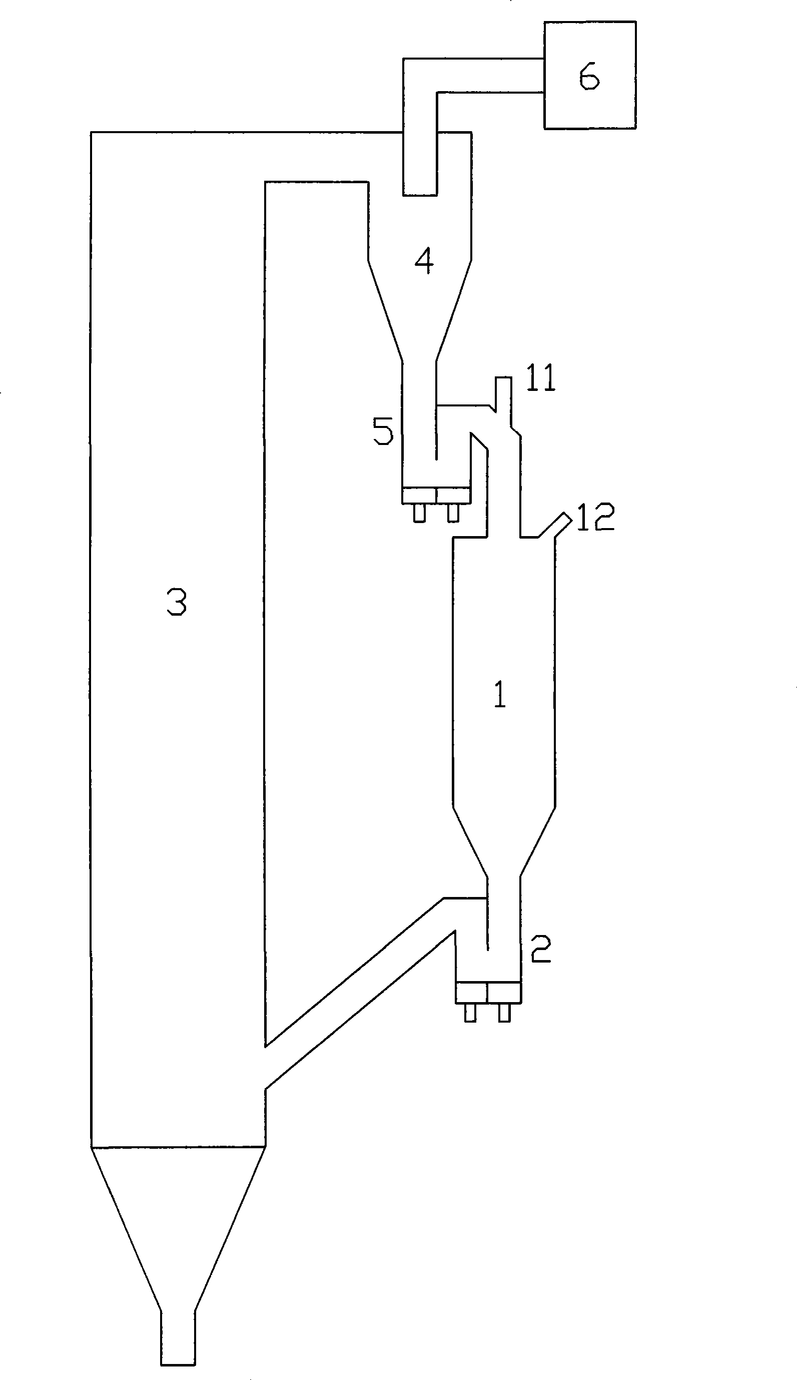
[0039] as attached figure 1 As shown, the coal undergoes pyrolysis reaction in the pyrolysis chamber to produce pyrolysis gas and semi-coke; the semi-coke is sent to the adiabatic combustion chamber for combustion, and the high-temperature materials produced by combustion are sent to the pyrolysis chamber to provide heat for the pyrolysis reaction; The combustion chamber is a circulating fluidized bed type;

[0040] Coal is added from the pyrolysis chamber; the oxygen content of the flue gas at the outlet of the combustion chamber is 0;

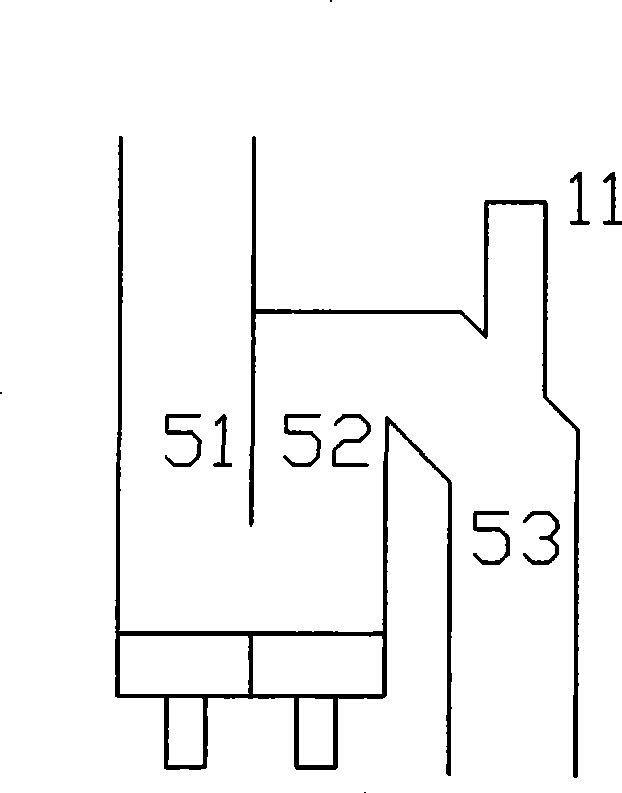
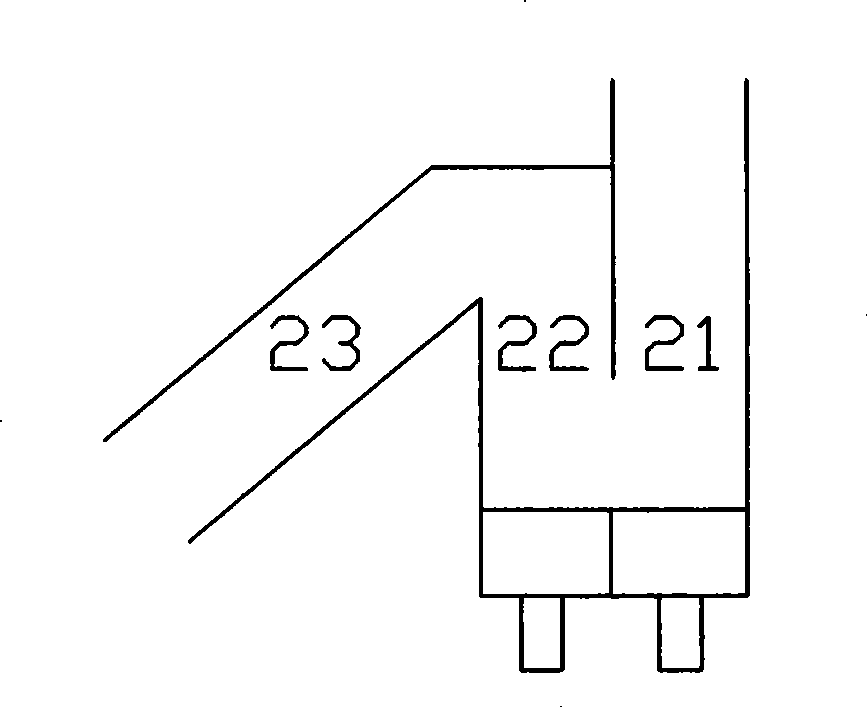
[0041] High-temperature materials enter the pyrolysis chamber from the top of the pyrolysis chamber through the feeder; semi-coke and low-temperature materials are discharged from the bottom of the pyrolysis chamber, and enter the combustion chamber through the pneumatic control valve;

[0042] The pyrolysis chamber is a low-speed bed, and the materials in the lower part flow in a downward moving bed under the action of the fluidizing wind i...

Embodiment 2

[0054] Such as Figure 4 As shown, the biomass undergoes pyrolysis reaction in the pyrolysis chamber to produce pyrolysis gas and semi-coke; the semi-coke is sent to the adiabatic combustion chamber for combustion, and the high-temperature materials produced by the combustion are sent to the pyrolysis chamber to provide heat for the pyrolysis reaction ; The combustion chamber is a circulating fluidized bed type;

[0055] Biomass is added from the pyrolysis chamber; the oxygen content of the flue gas at the outlet of the combustion chamber is 0;

[0056] High-temperature materials enter the pyrolysis chamber from the top of the pyrolysis chamber through the feeder; semi-coke and low-temperature materials are discharged from the bottom of the pyrolysis chamber, and enter the combustion chamber through the pneumatic control valve;

[0057] The pyrolysis chamber is a low-speed bed, and the materials in the lower part flow in a downward moving bed under the action of the fluidizin...

Embodiment 3

[0069] Such as Figure 5 As shown, the rubber undergoes pyrolysis reaction in the pyrolysis chamber to produce pyrolysis gas and semi-coke; the semi-coke is sent to the adiabatic combustion chamber for combustion, and the high-temperature materials produced by the combustion are sent to the pyrolysis chamber to provide heat for the pyrolysis reaction; The combustion chamber is a circulating fluidized bed type;

[0070] Rubber is added from the pyrolysis chamber; the oxygen content of the flue gas at the outlet of the combustion chamber is 0;

[0071] High-temperature materials enter the pyrolysis chamber from the upper part of the pyrolysis chamber through the feeder; semi-coke and low-temperature materials are discharged from the bottom of the pyrolysis chamber, and enter the combustion chamber through the pneumatic control valve;

[0072] The pyrolysis chamber is a low-speed bed, and the materials in the lower part flow in a downward moving bed under the action of the fluid...


PUM


Abstract

The invention provides a low velocity bed pyrolysis method and a device; fuel is added from a pyrolysis chamber so as to generate pyrolysis gas and semi-coke; the semi-coke is sent to a combustion chamber so as to be burned; the generated high-temperature material enters the pyrolysis chamber again from top of a material returning device, thus providing heat for the pyrolysis reaction; the combustion chamber is a circular fluidized bed type and the oxygen content of smoke at an outlet is zero; the semi-coke and low-temperature material are exhausted from the pyrolysis chamber and enter the combustion chamber through a pneumatic control valve; the pyrolysis chamber is internally provided with the low velocity bed; the fluidized air quantity of material returning device and the pneumatic control valve is adjusted so as to adjust the material height inside the pyrolysis chamber and the staying time of the material inside the pyrolysis chamber; the quantity of the air which enters the combustion chamber is adjusted so as to adjust the combustion heat exhausting quantity of the fuel, thus adjusting the temperature of the pyrolysis chamber; the pyrolysis chamber runs in a way of the combination of a low speed fluidized bed and a movable bed; the material has long staying time inside the pyrolysis chamber and complete pyrolysis reaction; the method and the device have various control ways of well controlling the temperature of the pyrolysis chamber. The method and the device can be used for coal, biomass and other carbonaceous refuse and alternative fuels, thus generating pyrolysis gas and coal tar.

Description

technical field [0001] The invention relates to the technical field of pyrolysis, and relates to a pyrolysis method and a pyrolysis device. Background technique [0002] In the coal pyrolysis process, controlling the temperature of the pyrolysis chamber is the key. The existing pyrolysis process that combines the pyrolysis chamber with the circulating fluidized bed combustion chamber uses the high-temperature circulating ash generated by the combustion of fuel in the combustion chamber to provide heat for the pyrolysis reaction, and the combination of combustion release heat and pyrolysis heat absorption Matching and balancing are generally achieved by circulating the ash flow and arranging the heating surface of the combustion chamber. The shunting of high-temperature circulating ash is to use mechanical or pneumatic methods to send part of it into the pyrolysis chamber as a heat source for pyrolysis. The more ash that enters the pyrolysis chamber, the higher the temperatu...

Claims


Application Information

Patent Timeline
IPC IPC(8): C10G1/00
Inventor 吕清刚高鸣那永洁李诗媛王东宇包绍麟孙运凯贺军
Owner INST OF ENGINEERING THERMOPHYSICS - CHINESE ACAD OF SCI
Why Eureka
Try Eureka