Ball separating device of bearing ball separating holder assembly machine

A cage and assembly machine technology, applied in the direction of bearing components, shafts and bearings, mechanical equipment, etc., can solve the problems of bearing steel ball and channel damage, ball needle bending, fracture, etc., to extend service life, not easy to break Or bending deformation, the effect of high work efficiency

Inactive Publication Date: 2009-02-11
无锡市江益轴承自动化设备有限公司
View PDF0 Cites 10 Cited by
  • Summary
  • Abstract
  • Description
  • Claims
  • Application Information

AI Technical Summary

Problems solved by technology

In the above ball distribution method, since the ball distribution needle and the ball distribution head are driven by the lifting mechanism to drop the ball, when the long distribution needle

Method used


Image

  • Ball separating device of bearing ball separating holder assembly machine
  • Ball separating device of bearing ball separating holder assembly machine
  • Ball separating device of bearing ball separating holder assembly machine

Examples


Example Embodiment

[0019] The specific embodiments of the present invention will be described in further detail below with reference to the accompanying drawings.

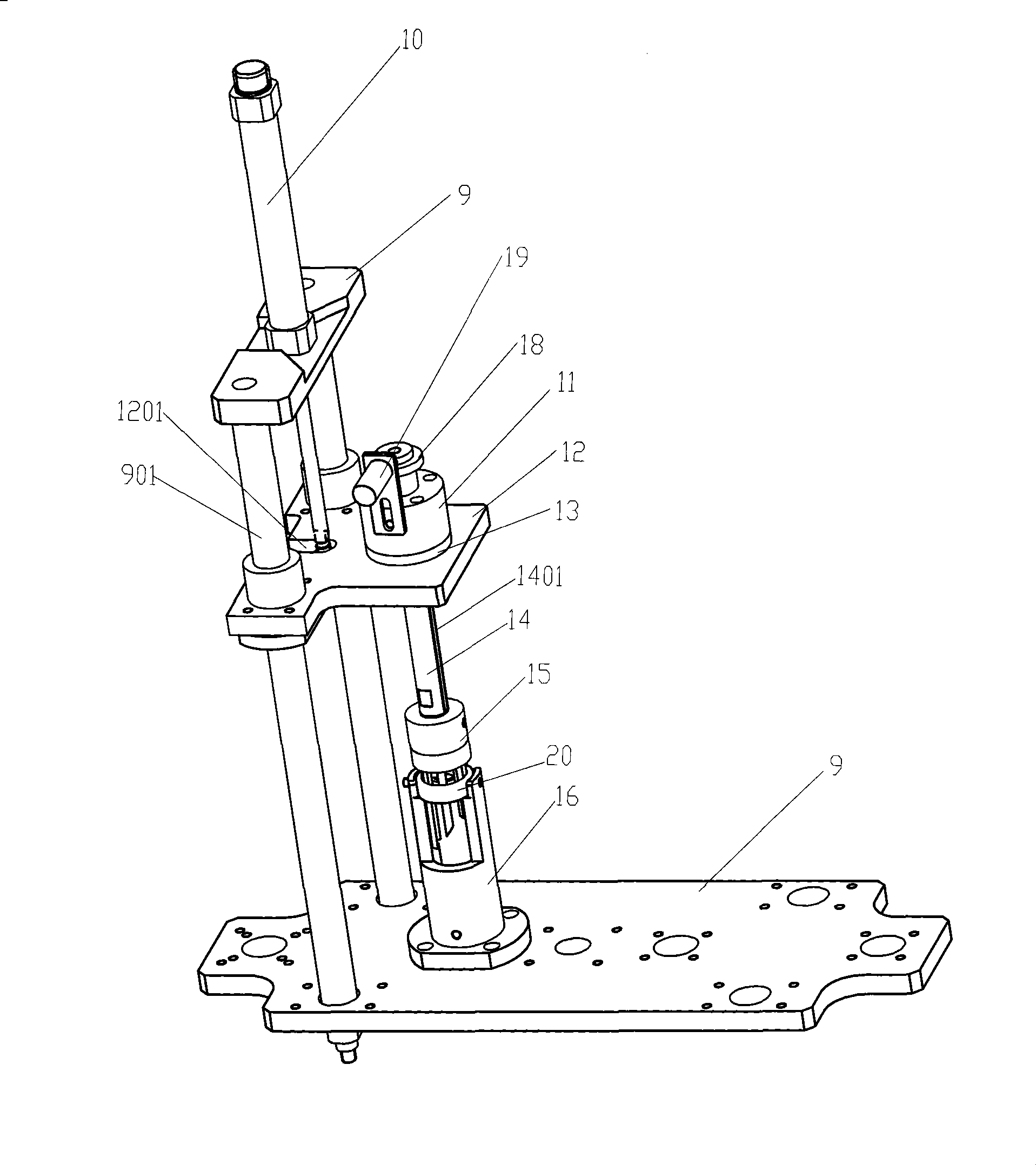
[0020] Such as image 3 As shown in 4, the present invention includes a frame 9 and an electronic control system (not shown in the figure). The upper part of the frame 9 is equipped with an air cylinder 10, and the frame 9 is equipped with two guide shafts 901, and a sliding device of the pallet 12 On the guide shaft 901, the piston rod of the cylinder 10 passes through the hole 1201 of the support plate 12, and the lifting head 17 of the support plate 12 is installed at the front end of the piston rod. When the piston rod of the cylinder 10 retracts, the front end of the piston rod The lifting head 17 pulls the pallet 12 to move upward along the guide shaft 901. When the piston rod of the cylinder 10 extends, the pallet 12 loses its downward restriction and depends on the weight of the pallet 12 and the mandrel mounted on it. Moving dow...


PUM


Abstract

The invention relates to a ball separating device of a bearing ball separating retainer assembly machine, and is characterized in that the ball separating device comprises a frame and an electric control system; a cylinder is arranged above the frame, a piston rod of the cylinder passes through a hole of a support plate, the front end of the piston rod is provided with a lifting and pulling head, the lower end of a mandrel is provided with a ball separating head, the upper end thereof is provided with an axle cap, a lower die of a locating bearing is arranged on the frame below the mandrel; the ball separating head includes a base which is arranged at the lower end of the mandrel, and a plurality of ball separating pins are sequentially arranged on the base by a sleeve chuck; the outer layer of the ball separating pin is made of metaformaldehyde or nylon, and the center thereof is embedded with a metal strip. By adopting the deadweight of the mandrel and a guide block to realize ball separating, the ball separating device does not cause damage to steel balls and the grooves on inner and outer rings and has high work efficiency. In addition, with the structure, the ball separating pin is not likely to snap, bend or deform during use, thus prolonging the service life of the ball separating pin and causing no scratch to the surfaces of the steel balls.

Description

Technical field [0001] The invention relates to a bearing manufacturing equipment, in particular to a ball separating device of a bearing ball separating cage assembly machine. Background technique [0002] In the bearing manufacturing process, the steel balls need to be evenly divided into the bearing inner and outer ring channels to facilitate the installation of the bearing ball cage. At present, most of the ball separating devices use positioning molds to withstand the inner and outer rings of the bearing. The steel balls can roll flexibly on the inner and outer rings of the bearing. The ball separating mold with a stepping motor is lowered and inserted between the inner and outer rings of the bearing, and the rotating ball drives the steel When the ball rotates, the ball-dividing mold hardly squeezes the steel ball when the steel ball rotates, so that the steel balls enter the steel ball groove of the ball-dividing mold to achieve the ball. This method of ball-dividing is lo...

Claims


Application Information

Patent Timeline
IPC IPC(8): F16C43/06
Inventor 王建忠郁彬曾祥斌
Owner 无锡市江益轴承自动化设备有限公司
Why Eureka
Try Eureka