Light source assembly high-power LED lamp and installation method thereof in lamp holder

A technology of LED lamps and LED light sources, which is applied in the direction of light sources, point light sources, semiconductor devices of light-emitting elements, etc., can solve the problems of screw or upper heat dissipation glue connection is not firm, easy to loose or even fall off the installation efficiency, to avoid the installation of screws Or the inconvenience of applying heat dissipation glue, and the effect of overcoming the weak connection

Inactive Publication Date: 2009-02-11
ENGLING
View PDF0 Cites 4 Cited by
  • Summary
  • Abstract
  • Description
  • Claims
  • Application Information

AI Technical Summary

Problems solved by technology

[0005] In order to solve the problems that the connection between the aluminum-based heat-conducting plate and the metal lamp cup is not firm using screws or upper heat-dissipating glue, it is easy to loosen or even fall off after long-term use, and its installation efficiency is low. The purpose of the present invention is to provide a heat-conducting aluminum-based The connection between the board and the metal lamp cup is tighter and firmer, and the high-power LED light source assembly and its installation method in the lamp cup can improve assembly efficiency

Method used


Image

  • Light source assembly high-power LED lamp and installation method thereof in lamp holder
  • Light source assembly high-power LED lamp and installation method thereof in lamp holder
  • Light source assembly high-power LED lamp and installation method thereof in lamp holder

Examples


Embodiment Construction

[0025] The present invention will be further described below in conjunction with accompanying drawing and specific embodiment;

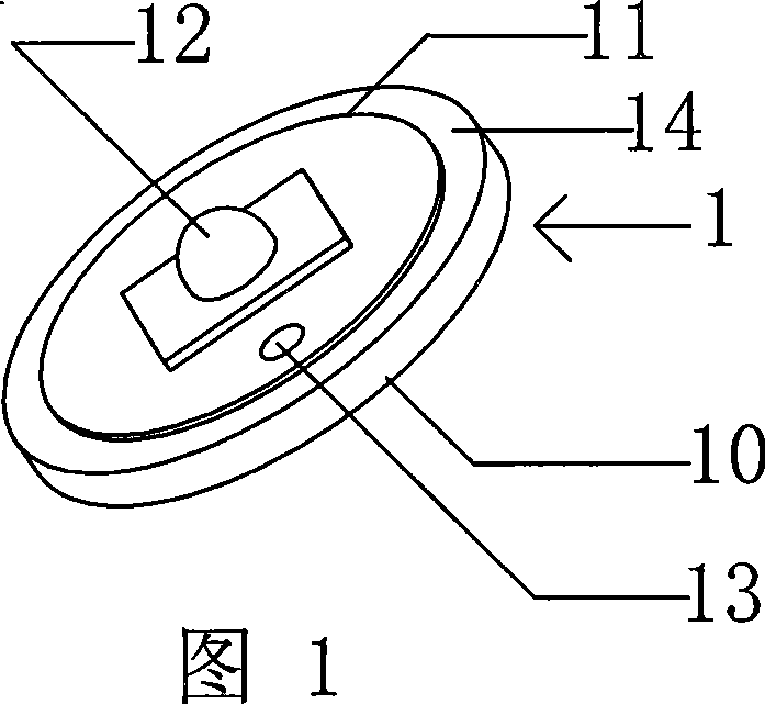
[0026] Please refer to Fig. 1; it is the high-power LED light source assembly 1 of the present invention. The light source assembly 1 uses a circular aluminum substrate with very good thermal conductivity as the heat conduction plate 10. The thickness of the heat conduction plate 10 is preferably between 5 and 10 mm. , a PCB circuit board 11 with the same shape as the aluminum-based heat-conducting plate 10 but slightly smaller than the aluminum-based heat-conducting plate 10 is packaged on the middle surface of the aluminum-based heat-conducting plate 10, so that an uncoated PCB circuit board is formed around the aluminum-based heat-conducting plate 10 11 covered aluminum base ring 14 . One or more high-power LEDs 12 are welded on the PCB circuit board 11 to form an electrical connection, and two external positive and negative power supply wires are...


PUM


Abstract

The invention discloses a light source component of a high power LED lamp and a installing method in a lamp cup thereof, and the light source component comprises an aluminum-based heat conducting plate, a PCB circuit plate encapsulated on the surface of the aluminum-based heat conducting plate and a high power LED, wherein, the PCB circuit plate is slightly smaller than the aluminum-based heat conducting plate and is arranged in the middle of the aluminum-based heat conducting plate, which leads the periphery of the aluminum-based heat conducting plate to form an aluminum-based circle that is not covered by the PCB circuit plate; the installing method is as follows: a light source component 1 is put in the lamp cup, and a metal punching rod provided with a convex block on the bottom end is put along an internal cavity of the lamp cup and leads the convex block to contact the surface of the aluminum-based circle; punching equipment or a hammer is used for acting on the top end of the metal punching rod to punch downwardly, and under the force, the partial surface of the aluminum-based circle that contacts the convex block deforms, and spreads towards the inner cavity wall of the lamp cup to be tightly clamped with each other, which avoids the defect that the connection between the aluminum-based heat conducting plate and the metal lamp cup is not firm, and increases the installing efficiency at the same time.

Description

technical field [0001] The invention relates to a high-power LED lamp, in particular to a high-power LED light source assembly of the lamp and its installation method in the inner cavity of a lamp cup. Background technique [0002] From the earliest carbon filament electric lamp invented by Edison with a lifespan of only 8 hours, to the tungsten filament incandescent lamp with a long service life; People have never stopped research on improving the service life, brightness and reducing energy consumption of lighting fixtures, especially in today's energy shortage, this aspect has become the direction of many people's unremitting efforts. [0003] The advent of LED (Light-emitting diode) light-emitting diodes undoubtedly heralds the arrival of a new era of solid-state light sources. This LED light-emitting diode uses the PN junction of semiconductor materials to add injected minority carriers and majority carriers. Excess energy is released in the form of light. It is a semi...

Claims


Application Information

Patent Timeline
IPC IPC(8): F21V29/00H01L23/36F21Y101/02F21V29/70F21Y115/10
CPCH01L2924/0002
Inventor 李霖
Owner ENGLING
Why Eureka
Try Eureka