Automatic feeding unit of stamping press

An automatic feeding and stamping machine technology, applied in the direction of presses, material forming presses, ceramic molding machines, etc., can solve the problems of easily damaged products, troubles, etc., and achieve the effect of improving production efficiency

Inactive Publication Date: 2009-02-18
王斌
View PDF2 Cites 36 Cited by
  • Summary
  • Abstract
  • Description
  • Claims
  • Application Information

AI Technical Summary

Problems solved by technology

However, for products with different cross-sections, such as bowl-shaped products, the mold cavity has a large upper opening and a smaller lower opening, or the lower opening is sealed, so it cannot pass through the mold cavity and drop from the lower opening to the conveyor belt below; In some cases,

Method used


Image

  • Automatic feeding unit of stamping press
  • Automatic feeding unit of stamping press
  • Automatic feeding unit of stamping press

Examples


Embodiment Construction

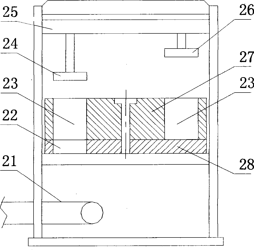
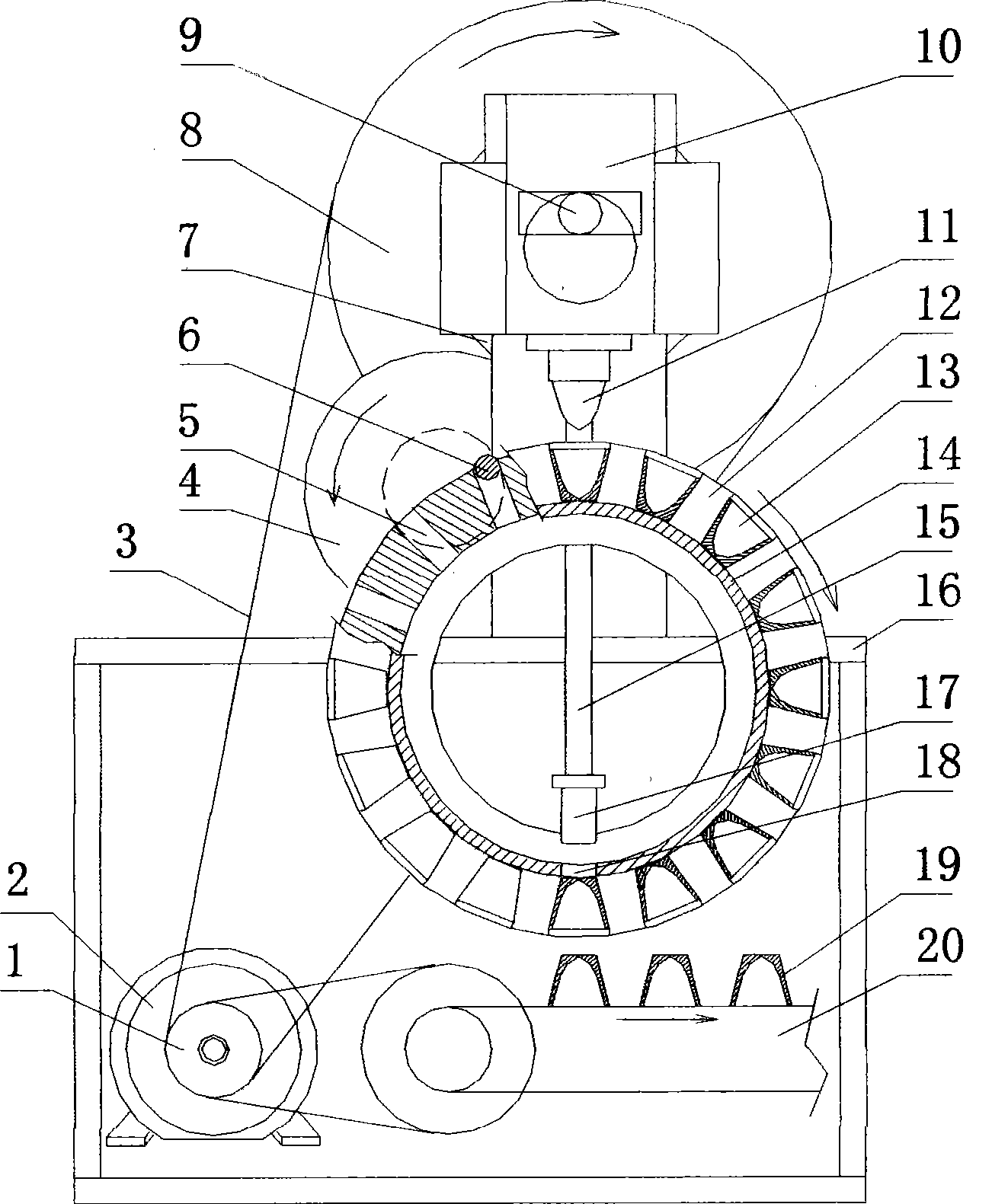
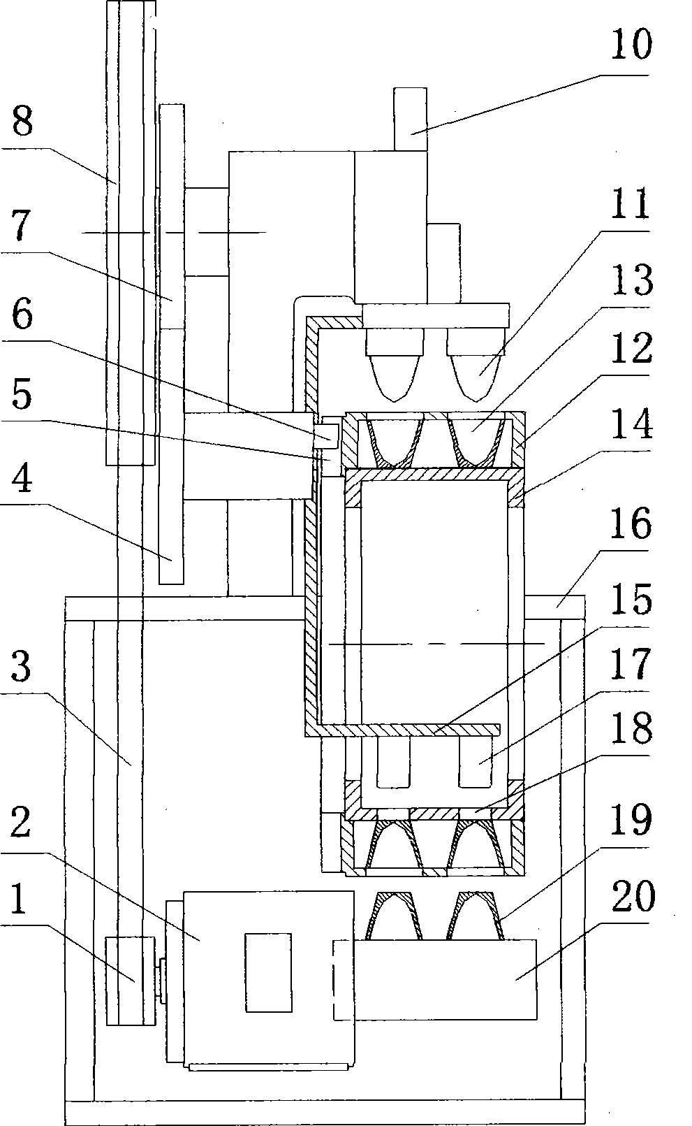
[0012] exist figure 2 and image 3 Among them, the motor (2) drives the belt pulley (1), and drives the flywheel (8) of the stamping mechanism to rotate through the transmission belt (3). The flywheel (8) drives the eccentric shaft (9) to drive the stamping slider (10) to reciprocate up and down. The stamping head (11) is installed at the bottom of the stamping slide block (10). A turntable workbench (12) is vertically arranged below the stamping head, and two rows of 32 radially installed die cavities (13) are evenly distributed on the circumferential surface of the workbench (12). Workbench (12) is installed on the workbench support frame (14), and support frame (14) is fixed on the bed frame (16). In the inner cavity of workbench (12), demoulding push rod (17) is installed downwards, and it is connected with stamping slide block (10) through push rod connecting frame (15) and does synchronous reciprocating motion. The bottom of the demoulding push rod (17) has a via ho...


PUM


Abstract

The invention relates to an automatic feeding device for punches, in particular to an automatic feeding device for compression-molding bowl-shaped products. The feeding device adopts a vertical turntable-type worktable rotating intermittently, and a plurality of circles of mold cavities are arranged on the circumference surface of the worktable in the radial direction. A punching slider which does up-down reciprocating motion is arranged above the worktable, and the motion direction of the punching slider is perpendicular to a rotating shaft line of the worktable. A mold release push rod is arranged in an inner cavity of the worktable downwards, and the push rod does reciprocating motion synchronously with the punching slider. A conveyer belt is arranged below the worktable. When a mold cavity follows the worktable to rotate to a punching position, punching process is carried out by a punching mechanism arranged above, and when the mold cavity follows the worktable to rotate 180 degrees to a downward mold release position, the mold cavity realizes natural overturning, so as to push a product onto the conveyer belt below from the bottom of the mold cavity through the mold release push rod arranged in an inner ring of the worktable.

Description

Technical field: [0001] The invention relates to an automatic feeding device for a stamping machine, in particular to an automatic feeding device for molding bowl-shaped products. Background technique: [0002] For molded products of equal cross-section, such as briquette, bricks, etc., the automatic production equipment has a typical structural scheme, such as figure 1 shown. This scheme adopts a horizontally arranged turntable workbench (27), and a plurality of through-hole die cavities (23) are distributed on the plane of the workbench (27), and a plurality of die cavities (23) are respectively arranged with feeding, stamping, Multiple stations such as demoulding, stamping head (26) and demoulding rod (24) are fixed on the movable beam (25), and reciprocate up and down with movable beam (25), when workbench (27) rotates intermittently, each Each mold cavity (23) will go through stations such as feeding, stamping, and demoulding successively. Below the workbench (27), t...

Claims


Application Information

Patent Timeline
IPC IPC(8): B30B15/30
CPCB30B11/12B28B5/12B30B11/10
Inventor 王斌
Owner 王斌
Why Eureka
Try Eureka