
Light modulation power supply and light modulation lamp

A technology for dimming power supplies and dimming lamps, which is applied in the field of dimming lamps and can solve problems such as light source flickering

Inactive Publication Date: 2009-02-18
SHANGHAI WILLIAMS LIGHTING
View PDF0 Cites 3 Cited by
  • Summary
  • Abstract
  • Description
  • Claims
  • Application Information

AI Technical Summary

Problems solved by technology

For example, when the load light source is a light-emitting diode, there will be an annoying flicker phenomenon at this time, that is to say, the light source will flicker during the brightness adjustment process

Method used


Image

  • Light modulation power supply and light modulation lamp

Examples


Embodiment Construction

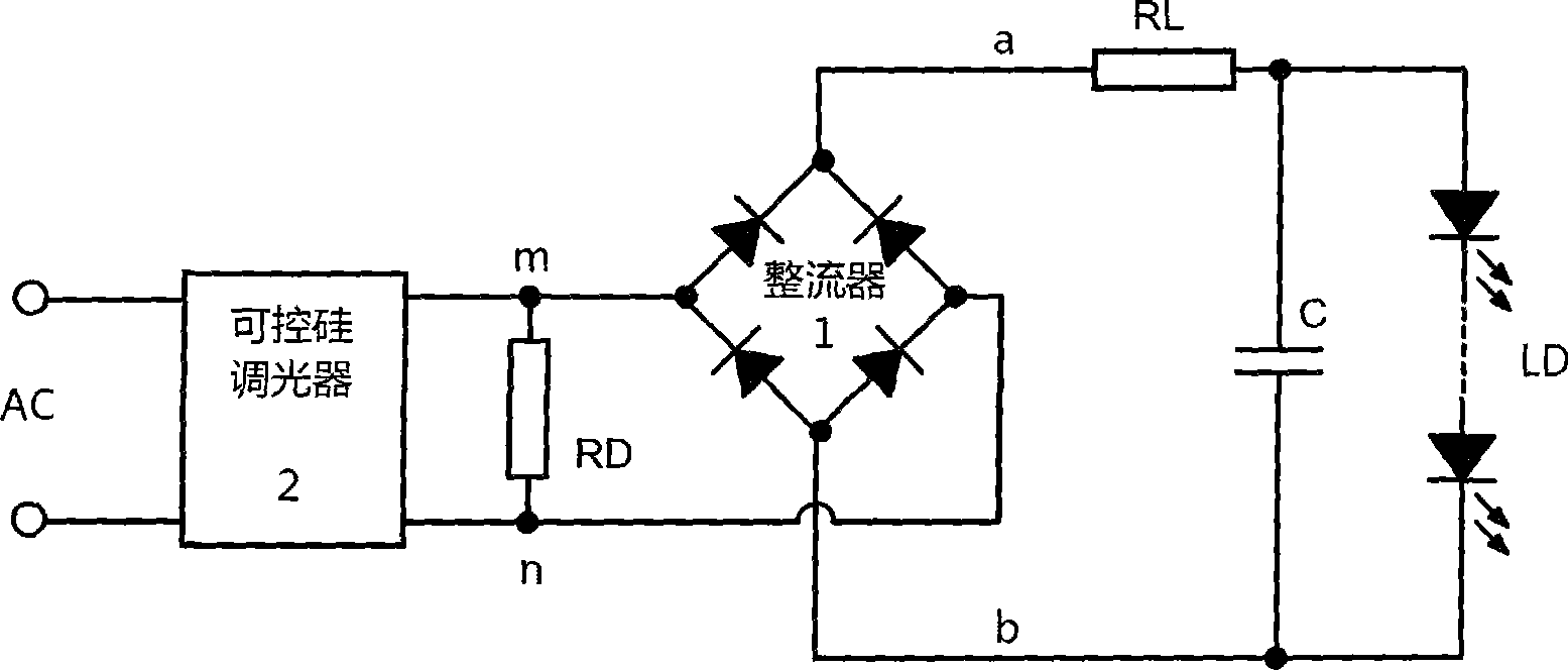
[0008] figure 1 The electrical schematic diagram of the dimming power supply and the dimming lamp according to the embodiment of the present invention is shown. see figure 1 , the dimming power supply includes a rectifier 1, connected to the power side of the rectifier 1 ( figure 1 TRIAC dimmer 2 in middle left). The improvement of the dimming power supply of the present invention lies in that the two power lines m and n between the rectifier 1 and the thyristor dimmer 2 are connected across the flashing resistor RD. The dimming lamp of the present invention is composed of a dimming power supply. The dimming lamp includes a dimming power supply and a light source load LD, and the light source load LD is connected to the output side of the rectifier 1 ( figure 1 middle right), the rectifier 1 supplies power to the light source load for lighting. When the dimming power supply is used to supply power to the light source load LD, the thyristor dimmer 2 is used to adjust the b...


PUM


Abstract

Disclosed are a light-adjusting power supply and a light-adjusting lamp which comprise a rectifier and a controllable silicon light adjuster connected with the power supply side of the rectifier; the light-adjusting power supply and the light-adjusting lamp are characterized in that a flash elimination resistor is in bridge connection with two power wires between the rectifier and the controllable silicon light-adjuster. At least a LED used as the light source load is connected between the other end without serial connection of the rectifier of the light-adjusting lamp and the other output end of the rectifier. The light-adjusting power supply and the light-adjusting lamp eliminate the flash phenomenon generated when the light source used as the load is adjusted to be in the low brightness.

Description

technical field [0001] The invention relates to a dimming power supply and a dimming lamp containing the dimming power supply. Background technique [0002] In the prior art, a dimming power supply is commonly used to supply power to a light source load and perform brightness adjustment control on the brightness of the light source in the light source load, so as to realize lighting with variable brightness. There is a type of dimming power supply, usually with a thyristor dimmer connected to the power supply side of its rectifier. For this kind of dimming power supply, when the brightness of its load light source is adjusted to a low level by the thyristor dimmer, an abnormal phenomenon will appear. For example, when the load light source is a light emitting diode, there will be an annoying flicker phenomenon at this time, that is, the light source will flicker during the brightness adjustment process. Contents of the invention [0003] In order to solve the above probl...

Claims


Application Information

Patent Timeline
Patent Type & Authority Applications(China)
IPC IPC(8): F21V23/00F21V23/02H05B37/02F21Y101/02F21Y115/10
Inventor 俞志龙
Owner SHANGHAI WILLIAMS LIGHTING
Learn More