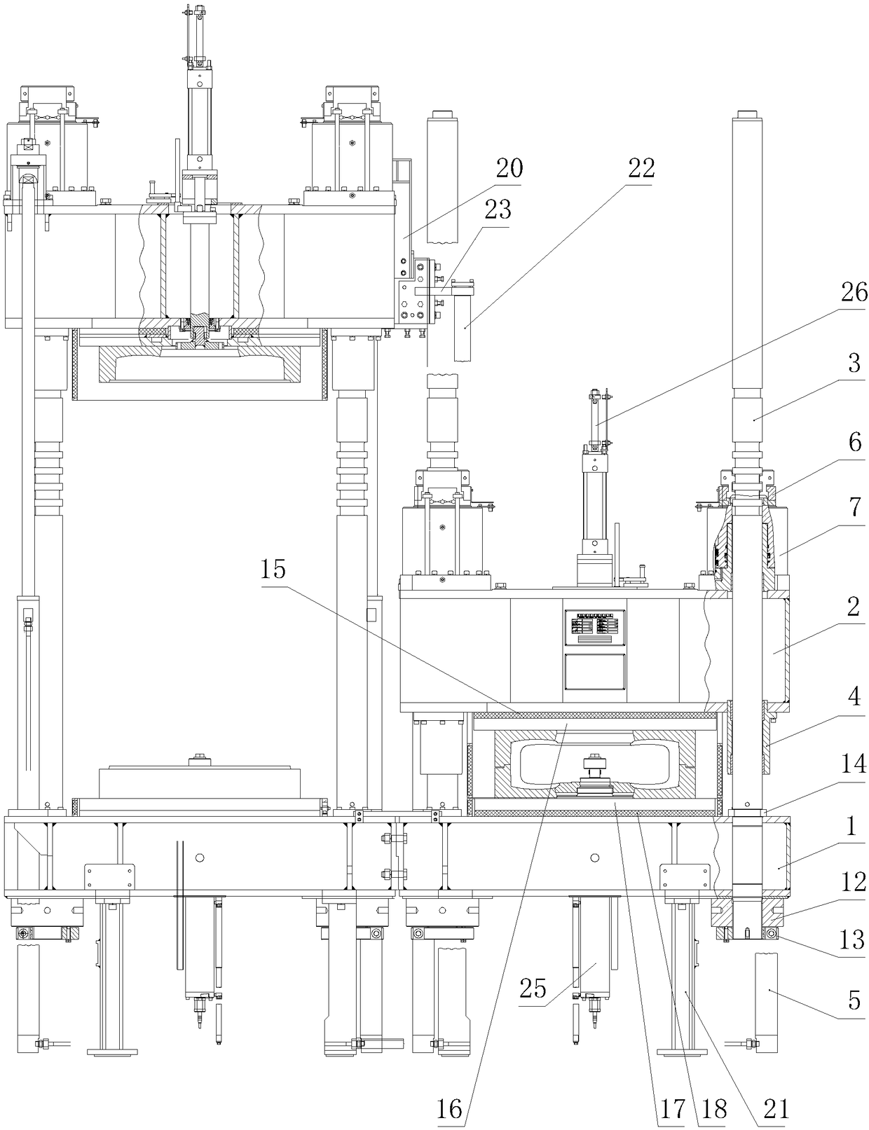
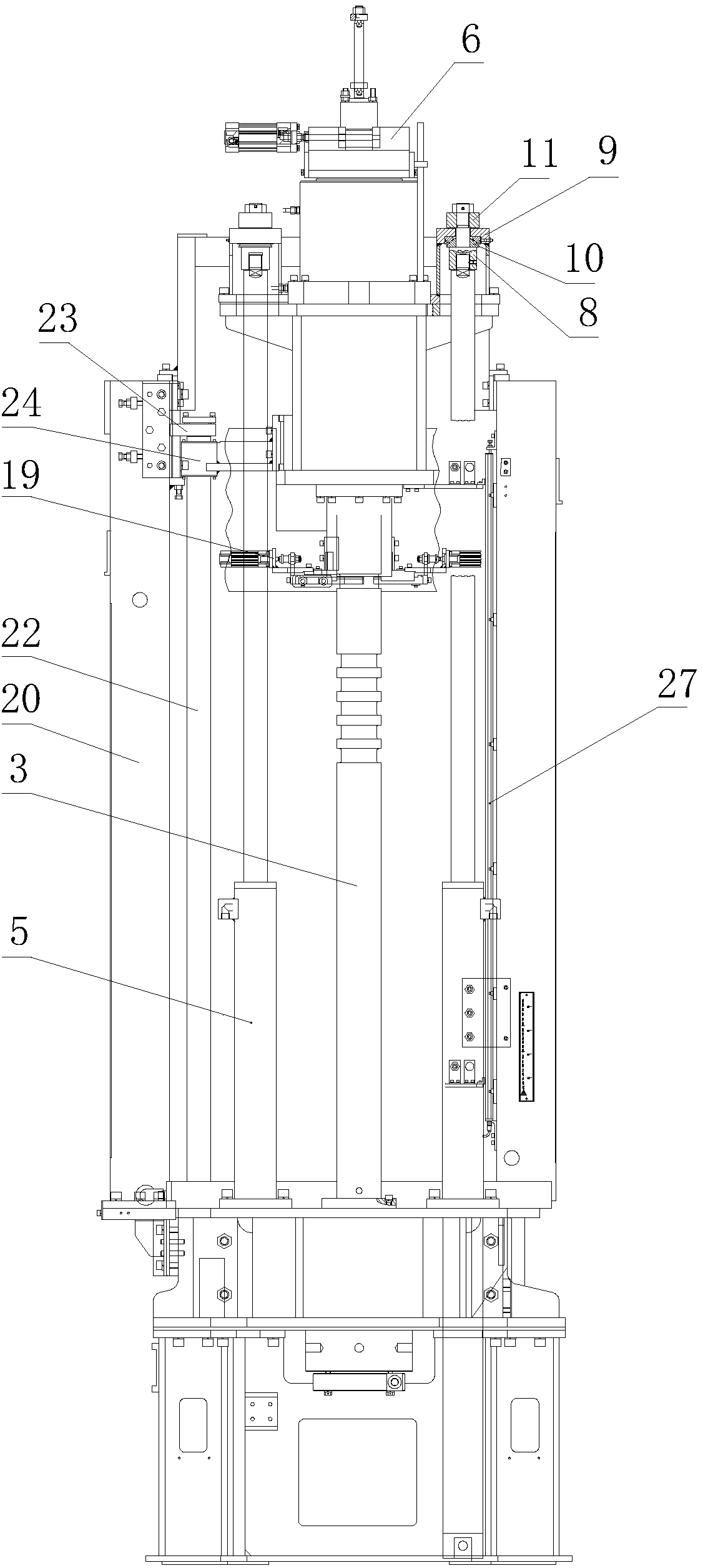
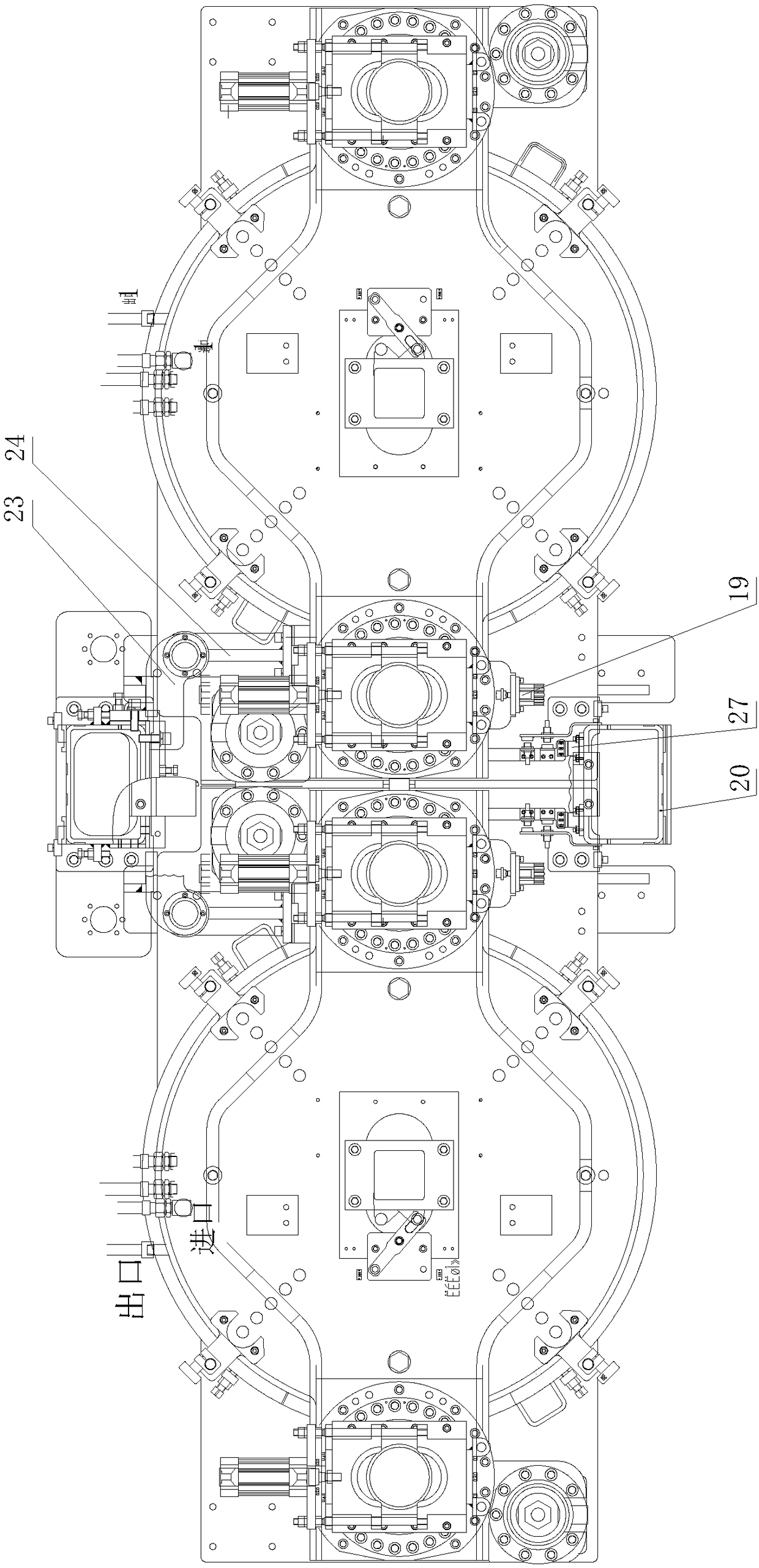
[0008] 1. Since the left and right beams are integral structures, the
middle column is thick, and the columns at the left and right ends are thin. When performing single-mode
vulcanization or left and right
vulcanization of tires of different specifications, the left and right mold forces are different, and the beam will tilt at this time. side, the mold is not parallel and easily damaged, so it cannot be used for single-mode
vulcanization and simultaneous vulcanization of tires of different specifications;
[0009] 2. Since the beam and the base are integral structures, the manufacture of the product is difficult, the production cost is high, and the
transportation cost is also high;
[0010] 3. Since the
middle column is tall and one, and the left and right ends of the columns are low, the crossbeam may rotate around the center column after the mold is opened away from the left and right ends of the columns, which will cause the deviation of the lower and upper molds, and repeat the centering Poor performance, when the mold is closed again, it is difficult for the beam to be aligned and enter the columns at the left and right ends, or even unable to enter;
[0011] 4. Since the
middle column is thick and the columns at the left and right ends are small, the elastic stretch length of the columns is different under the action of the mold tension, resulting in flashing of non-parallel tires when the mold is closed;
[0012] 5. Since the centerlines of the three columns are in the same plane, the role of the columns here is to guide the lifting of the beam and bear the tension of the mold. It cannot
well control the lifting of the beam in the limited space, and the lifting of the beam is unstable. It cannot prevent the beam, the upper heating plate, The
moving parts of the upper mold tilt forward and backward when the mold is opened and closed; what is fatal is that the center of gravity deviates from the center of the model, causing the guide rod to tilt to one side of the guide sleeve. When the mold is opened to the top, the beam, the upper heating plate, and the upper mold The inclination is larger, and the long-term lifting and sliding operation causes the
copper sleeve of the guide sleeve to
wear and tear and the gap is large. When the mold is opened to the top, the beam, the upper
hot plate, and the upper mold tilt more seriously, and the shaking is more severe. The above problems are likely to cause: a. Damage The upper mold of the movable mold; b, the upper
hot plate and the lower
hot plate are not parallel, and the upper and lower molds are not parallel; c, the
piston rod of the opening and closing mold cylinder is bent, and the
piston rod seal leaks; d, the centering
repeatability of the lower and upper molds is poor;
[0013] 6. Since the pressurized oil cylinder is installed between the base and the lower supporting plate (supporting the lower hot plate and the lower mold), the maintenance of the pressurized oil cylinder is difficult; when the mold is closed, the pressurized oil cylinder pushes the lower supporting plate and the lower mold without guidance Moving upwards, the centering
repeatability of the lower and upper molds is poor, and the quality of the vulcanized tires is unstable;
[0014] 7. There is
no detection device for the lifting position and displacement of the beam, and the adjustment and replacement of the mold cannot be digitally set and intelligently detected and controlled.
[0016] 1. Since the upper plate and the lower plate are of plate structure, the plate structure is a
solid thick steel plate. The thick steel plate is not only heavy, but also the material blanks are not easy to purchase, so special purchase is required, and the cost is high
[0017] 2. Since the upper plate and the lower plate are plate-type structures, the rigidity is poor. When the mold is clamped and the force is added, the front and rear parts of the supporting hot plate far away from the pressurized force position have
large deformation and
large deflection, resulting in the front and rear parts of the lower and upper molds. If there is no contact, the tire will produce flash;
[0018] 3. Since the centerlines of the two guide rods of the single-mode are in the same plane, the function of the guide rods here is to guide the upper plate to lift and bear the tension of the mold. It cannot
well control the lift of the upper plate in the limited space, and the lift of the upper plate is unstable. It cannot prevent the
moving parts such as the upper plate, the upper hot plate, and the upper mold from tilting forward and backward when the mold is opened and closed. When the upper plate, upper hot plate, and upper mold are tilted more, the
copper sleeve of the guide sleeve is worn and the gap is large due to the long-term lifting and sliding operation. When the mold is opened to the top, the upper plate, upper hot plate, and upper mold tilt more seriously and shake Even worse, the above problems will also cause: a. Damage to the upper mold of the active mold; b. The upper hot plate is not parallel to the lower hot plate, and the upper and lower molds are not parallel; c. The
piston rod of the opening and closing mold cylinder is bent, and the
piston rod seal leaks ; d. The centering
repeatability of the lower and upper molds is poor; e. The position
magnet of the displacement detection device cannot slide smoothly on the displacement sensor and is easily damaged, causing the displacement sensor to loosen and shift, resulting in inaccurate detection and resulting in the limit position of the mold opening (closed The initial drop position of the mold), the secondary setting position, and the mold clamping position are not accurately detected. Even at the mold clamping position, the mold locking slider of the mold
locking mechanism cannot enter the guide rod annular groove and cannot lock the mold. At this time, it needs to be replaced, repaired, Manually re-detect the set position data; f. The gear of the displacement detection device deviates from the rack, and the gear cannot mesh well with the rack, resulting in inaccurate detection, resulting in the limit position of mold opening (the initial drop position of mold closing), and the secondary setting The position and mold clamping position detection is inaccurate, and even at the mold clamping position, the clamping slider of the clamping mechanism cannot enter the annular groove of the guide rod and cannot lock the mold. At this time, it needs to be replaced, repaired, and the set position data must be manually re-checked;
[0019] 4. Since the displacement sensor device of the displacement detection device adopts a contact-type external telescopic displacement sensor and a position
magnet, there is no proximity switch for changing molds; after long-term use, the position
magnet slides on the displacement sensor, causing the guide rail of the displacement sensor and the position magnet to
wear out. The sliding tension of the position magnet causes the displacement sensor to loosen and shift, which also leads to inaccurate detection, resulting in inaccurate detection of the mold opening limit position (the initial drop position of the mold closing), the secondary setting position, and the mold closing position, and even the mold locking mechanism at the mold closing position. The mold clamping slider cannot enter the annular groove of the guide rod and the mold cannot be clamped. At this time, it needs to be replaced, repaired, and the set position data must be manually re-checked;
[0020] 5. Since the two guide rods are fixed on the upper plate and are opened and closed together with the upper plate, the upper hot plate and the upper mold, when the mold is closed to the end, the guide rods must extend into the pit of the equipment foundation at this time, increasing the user’s Basic cost of excavation equipment


