Building-integrated water container heat collection type solar energy utilization method

A technology of solar energy and solar heat collectors, applied in the field of solar energy utilization, can solve the problems of affecting the city landscape, large heat loss, and inability of solar water heaters, etc., and achieves the effect of significant environmental protection benefits and improved cost performance

Inactive Publication Date: 2009-02-18
北京正仁远大垃圾处理科技有限公司
View PDF0 Cites 2 Cited by
  • Summary
  • Abstract
  • Description
  • Claims
  • Application Information

AI Technical Summary

Problems solved by technology

[0005] One is that the heat collecting tube type is generally used, and the water tank is arranged on the upper end of the heat collecting tube and is closely connected with the heat collecting tube; the pressure-bearing type is used to push (press) hot water into the water tank through the heat collecting tube, and the water tank is set outdoors, and the heat loss is relatively small. The second is that the water is heated mainly by the heat collecting tubes, and there is a certain distance between the heat collecting tubes, the actual heat collecting area is more than 30% less than the plate heat collecting area, and the heat utilization rate is not high; the third is that the heat collector and the roof A certain inclination is formed to form an air convection channel, which takes away a lot of heat and causes a large heat loss; fourth, the water storage capacity of the hot water tank is very limited, and can only meet the hot water supply for two to three people; It is made of expensive copper or copper-aluminum alloy, and the water tank is also made of high-priced pond porcelain or stainless steel, which greatly increases the cost of construction. It is not really integrated with the building, but more is to use brackets to support the heat collector and water tank on the roof, which affects the cityscape; Seventh, the heat collector pipes generally have problems such as scaling, blockage, and frost cracking. Some areas cannot be used in winter;

Method used


Image

  • Building-integrated water container heat collection type solar energy utilization method

Examples


Embodiment Construction

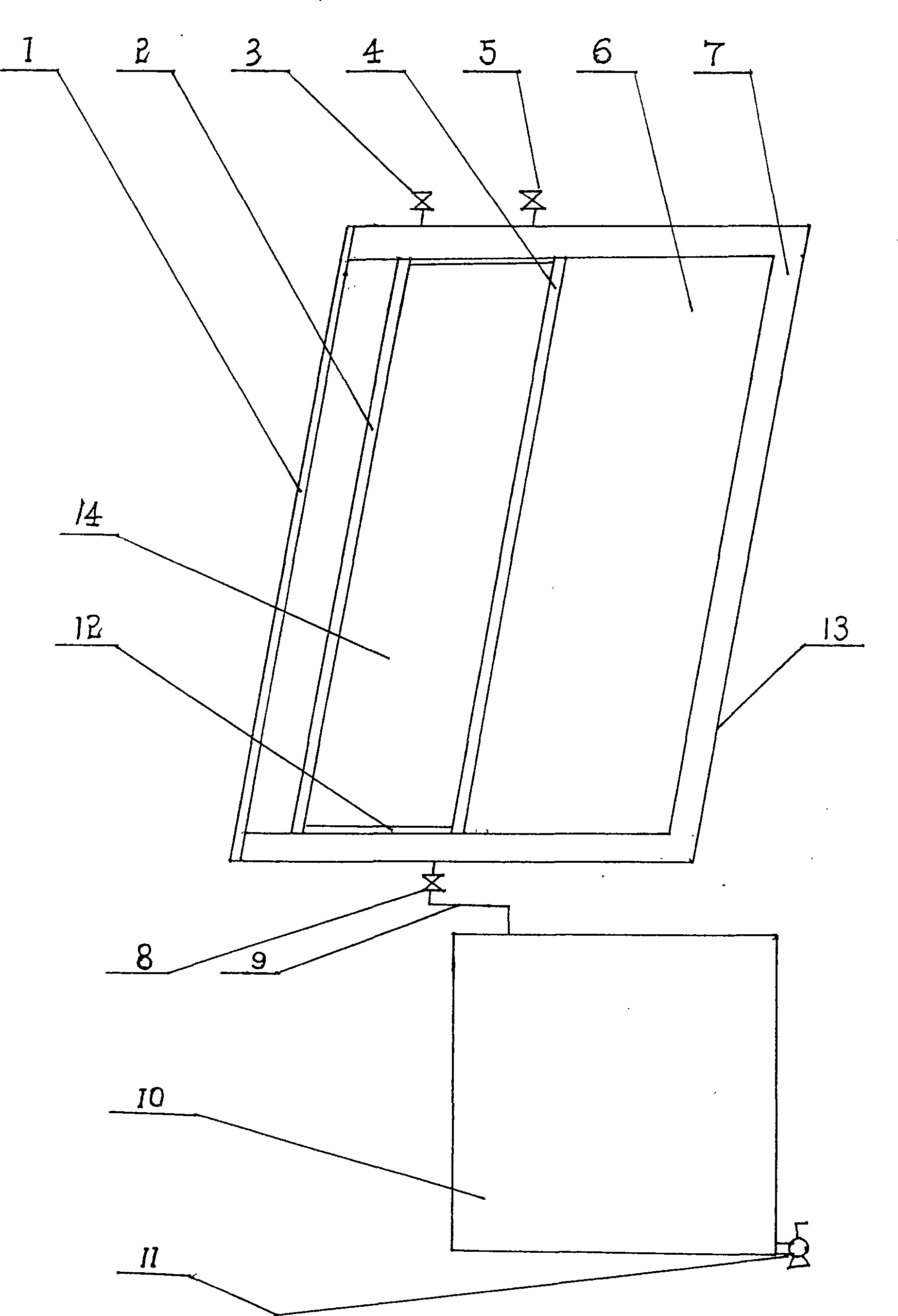
[0020]In the accompanying drawings, the heat collector cover (1) is made of materials such as glass or fiberglass with better light transmittance; It can be made of stainless steel or ordinary steel plate or glass, and its surface is sprayed with a selective paint with good heat absorption; the distance between the cover plate of the hot water tank (2) and the cover plate of the heat collector (1) is set to 1 cm- 10 centimeters, with 2 centimeters-5 centimeters being the best; the cold water control valve (3) of the hot water tank is an electromagnetic control valve, and when the cold water is filled with the hot water tank (14), it is automatically closed; the bottom plate of the hot water tank (4 ) and the box plate (12) of the water collecting tank (14) do not need to be made of expensive materials such as copper or copper aluminum alloy (known solar water heaters generally use copper as the heat collecting tube), and steel plates with relatively low prices can be used Meta...


PUM


Abstract

The invention relates to a solar energy utilization method which adopts a heat-collecting water tank integrated with the building and belongs to the solar energy utilization field. The solar energy heat-collecting device is integrated with the inclined roof, wall body or balcony retaining plate of the building to a whole; the cost is reduced greatly while the solar energy is utilized to the maximum limit; the heat-collecting pipe heat-collecting mode is replaced by the water tank heat-collecting mode to improve the solar energy utilization rate while the cost is reduced and the heat-collecting area is increased; the water storage tank is arranged in the room to reduce the heat loss when the water tank is arranged outside and improve the solar energy utilization rate while the manufacturing cost of the water tank is reduced; the solar energy utilization method not only can utilize the solar energy to supply hot water, but also can utilize the solar energy for heating and is a significant breakthrough and innovation on the solar energy utilization aspect.

Description

Technical field [0001] The invention relates to a solar energy utilization method, in particular to a water tank heat collection type solar energy utilization method integrated with a building, belonging to the field of solar energy utilization. Background technique [0002] At present, there are mainly two known methods for utilizing solar energy, one is a photoelectric utilization method in the form of solar photovoltaic power generation; the other is a photothermal utilization method in which solar water heaters are used as the main method. [0003] Because the silicon crystal (single crystal silicon or polycrystalline silicon) materials that must be used in photovoltaic power generation are expensive, the investment in photovoltaic power generation per kilowatt is as high as RMB 50,000-70,000, which is 5-10 times that of conventional power generation; the cost per kilowatt-hour is as high as 3 -4 yuan, if it is used for civilian electricity, it needs a large amount of su...

Claims


Application Information

Patent Timeline
IPC IPC(8): F24J2/00F24J2/46E04D13/18F24S10/40
CPCY02B10/20Y02E10/40Y02E10/44
Inventor 林善斌章大明
Owner 北京正仁远大垃圾处理科技有限公司
Why Eureka
Try Eureka