
Ground imbedded high-capacity optical cable connection box

An optical cable junction box and large-capacity technology, applied in the direction of fiber mechanical structure, etc., can solve the problems of unable to meet actual needs, no accident early warning system, long maintenance time, etc., to achieve simple and fast construction, easy maintenance and installation, and reduce land occupation. area effect

Active Publication Date: 2009-02-18
北京优通泰达电气新技术发展有限公司 +1
View PDF0 Cites 9 Cited by
  • Summary
  • Abstract
  • Description
  • Claims
  • Application Information

AI Technical Summary

Problems solved by technology

The disadvantage of the optical cable transfer box is that it is inconvenient to maintain and there is no accident warning system, so once a damage accident occurs, the maintenance takes a long time
Moreover, the communication capacity is small, which cannot meet the actual needs

Method used


Image

  • Ground imbedded high-capacity optical cable connection box
  • Ground imbedded high-capacity optical cable connection box
  • Ground imbedded high-capacity optical cable connection box

Examples


Embodiment Construction

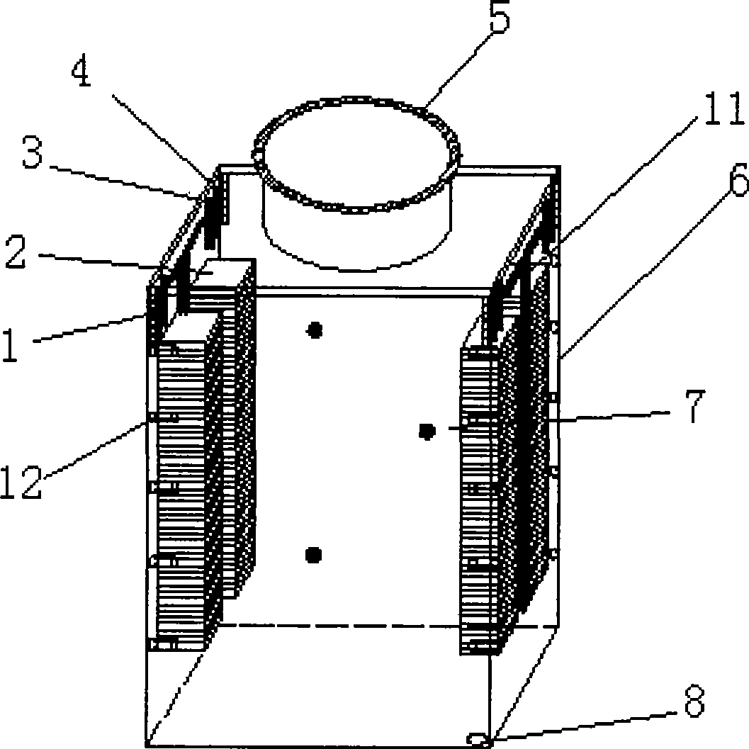
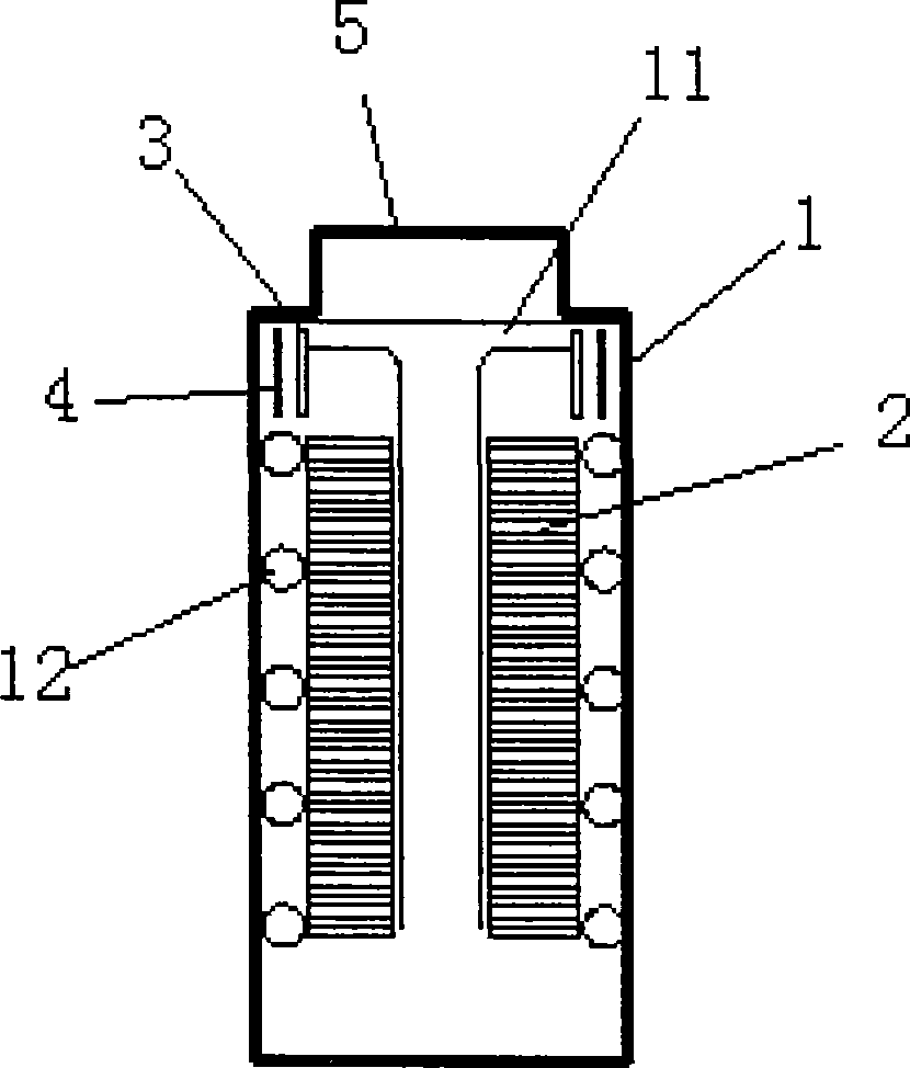
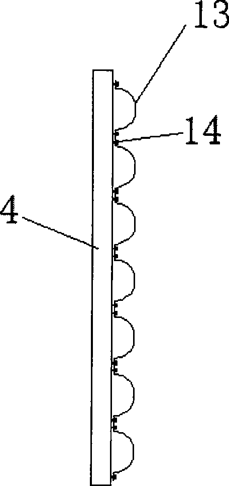
[0018] The buried large-capacity optical cable transfer box proposed by the present invention has a structure such as figure 1 Shown, comprise box body 6 and sealing box cover 5. The box body 6 is equipped with a cable inlet 1, an optical cable rack 17, an optical cable reinforcement core fixing card 3, an optical cable fixing card 4, a fiber guide groove 11, a fusion fiber tray 2, a jumper tray fiber barrel 12, and a retractable pedal Point 7 and emergency drain 8. The cable inlet 1 , the fiber optic cable strengthening core fixing card 3 and the fiber optic cable fixing card 4 are respectively located on the upper side wall of the box body 6 . The optical cable running rack 17 is positioned on the walls around the top of the casing 6 . Such as figure 2 As shown, the fiber splice tray 2 is located on two opposite side walls of the box body 6, the fiber guide slot 11 is connected between the fiber optic cable reinforcement core fixing card 3 and the fiber splice tray 2, an...


PUM


Abstract

The invention relates to a underground large capacity optical cable connecting box, which belongs to the optical cable transmission technique field. The connecting box includes a box body and a seal cover, and a cable inlet, an optical cable routing bracket, an optical cable core-strengthening fixed card, an optical fiber fixed card, a guide fiber groove, a fusion fiber tray, a jumping wire coil fiber case and the like are arranged in the box body. The cable inlet, the optical cable core-strengthening fixed card and the optical fiber fixed card are respectively positioned on the sidewall of the upper part of the box body. The optical cable routing bracket is positioned on the around wall of the upper part of the box body, and the fusion fiber tray is positioned on two opposite walls in the box body. The guide fiber groove is connected between the optical cable core strengthening fixed card and the fusion fiber tray, and jumping wire coil fiber case is arranged at one side of the fusion fiber tray. The connecting box has the advantages that: the construction is simple and swift, the construction can be easily executed in downtown flourishing sections, can not affect the traffic, and can effectively reduce the occupied land area of downtown streets. The underground connecting box can be prevented from damaging, so as to ensure the secure communication. The connecting box has large capacity, and can be applied to the convergence layer and the optical cable inlet and outlet layers where optical fiber is centralized.

Description

technical field [0001] The invention relates to an underground large-capacity optical cable transfer box, which belongs to the technical field of optical cable transmission. Background technique [0002] The optical cable transfer box is an interface device used for the backbone optical cable and distribution optical cable node in the optical fiber metropolitan area network, which can realize the fusion splicing, disk storage, distribution and scheduling of optical fibers. With the increasing opening of the telecommunications market, operators are stepping up the construction of their own optical cable metropolitan area network. The large-scale construction of optical cable metropolitan area network will greatly increase the demand for optical cable transfer boxes. Existing fiber optic cable transfer boxes are generally placed on the ground, which has the disadvantages of affecting city appearance, affecting traffic, occupying land resources, and not meeting the requirements...

Claims


Application Information

Patent Timeline
Patent Type & Authority Applications(China)
IPC IPC(8): G02B6/44
Inventor 张世勇丁占武焦煜叶巍刘磊陈平靳硕李纲姜长青刘月强
Owner 北京优通泰达电气新技术发展有限公司
Learn More