
Shadow mask type plasma display board

A plasma and display panel technology, applied in the direction of solid cathode parts, cold cathode tubes, etc., to achieve the effect of improving luminous brightness and luminous efficiency and simple process

Inactive Publication Date: 2009-02-18
SOUTHEAST UNIV
View PDF0 Cites 2 Cited by
  • Summary
  • Abstract
  • Description
  • Claims
  • Application Information

AI Technical Summary

Problems solved by technology

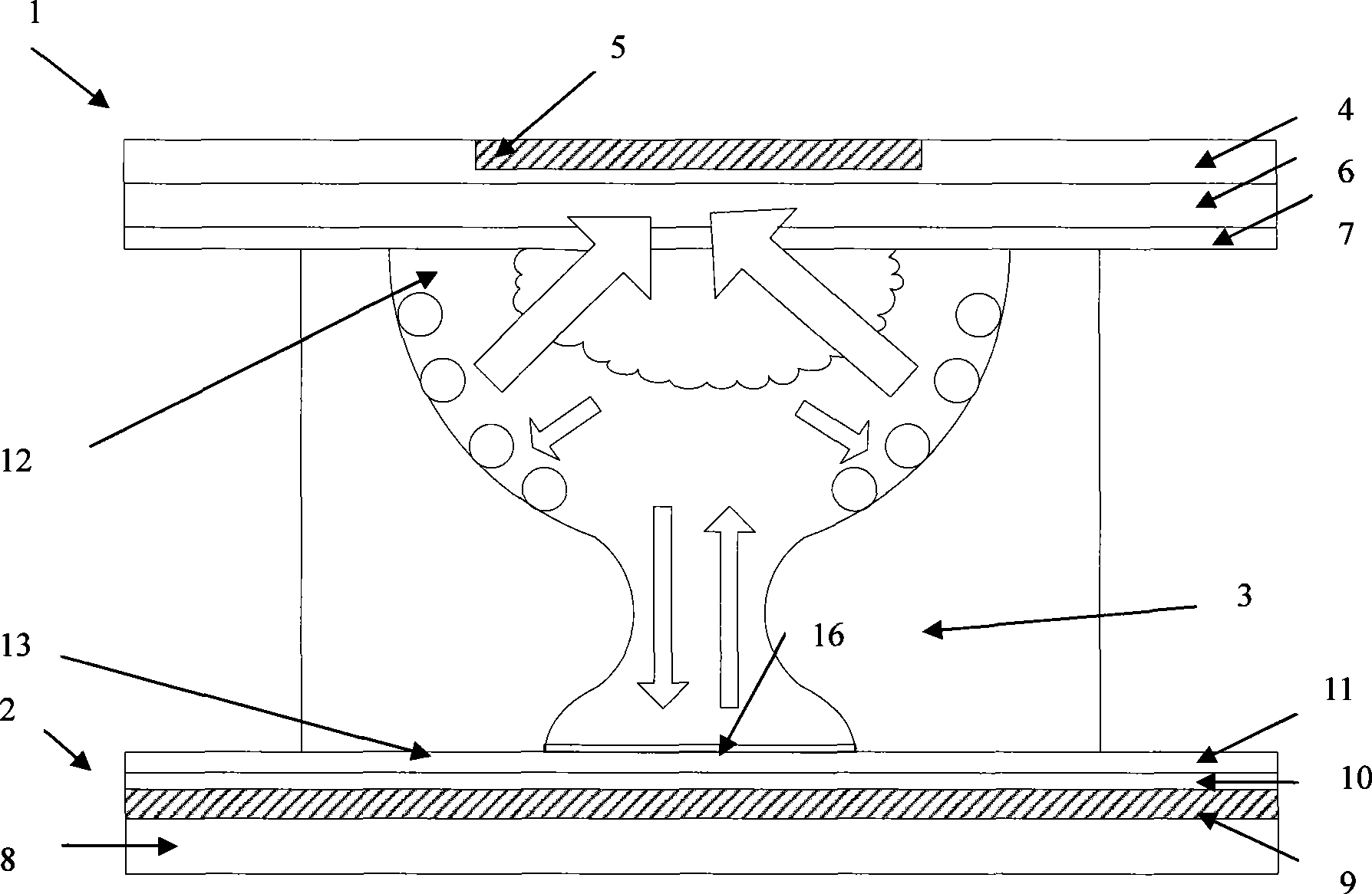
[0003] The purpose of the present invention is to solve the problems caused by the opposite discharge in the existing shadow mask plasma display panels, and to invent a shadow mask plasma display panel with improved brightness and luminous efficiency. layer of reflective film

Method used


Image

  • Shadow mask type plasma display board
  • Shadow mask type plasma display board
  • Shadow mask type plasma display board

Examples


Embodiment 1

[0018] Such as Figure 1-4 shown

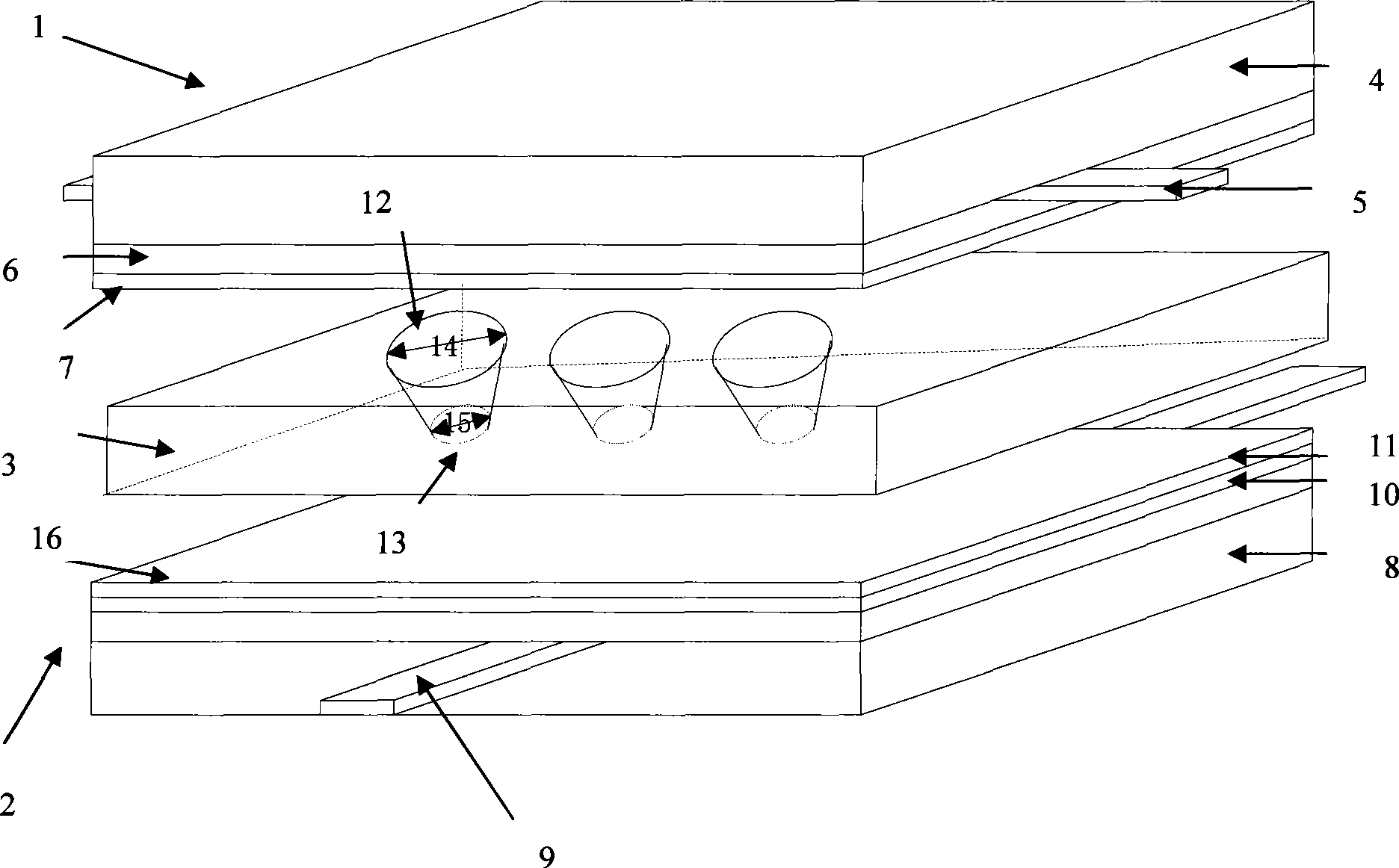
[0019] A shadow mask type plasma display panel, such as figure 1 As shown, it includes a front substrate 1, a rear substrate 2, and a shadow mask 3, wherein the shadow mask 3 is packaged between the front substrate 1 and the rear substrate 2, and the front substrate 1 includes a front substrate glass substrate 4, scanning electrodes 5, The front substrate dielectric layer 6, the front substrate protective film 7, and the scanning electrodes 5 are arranged in parallel on the front substrate glass substrate 4, the front substrate dielectric layer 6 covers the scanning electrodes 5, and the front substrate protective film 7 covers the front substrate dielectric layer 6 Above; the rear substrate 2 includes a rear substrate glass substrate 8, an address electrode 9, a rear substrate dielectric layer 10 and a rear substrate protective film 11, and the address electrode 9 is arranged in parallel on the rear substrate glass substrate 8, and the rear...

Embodiment 2

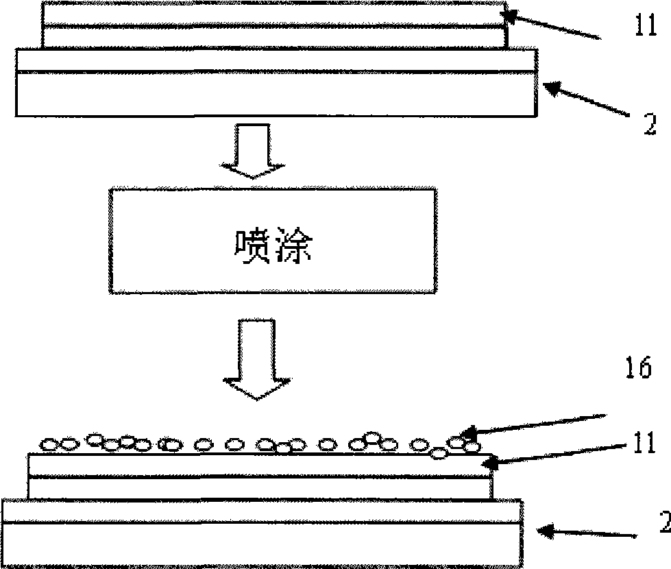
[0026] In the first embodiment above, the diffuse reflection film 16 can also be formed of SiO with a thickness of 50 nm to 1 μm by continuous vapor deposition while forming the film 11. 2 Reflective film. The working principle of the shadow mask type plasma display panel constructed in this embodiment is the same as that in the first embodiment.


PUM


Abstract

The invention relates to a plasma display panel, especially a shadow mask type plasma display panel. The invention comprises a front base plate, a back base plate, a shadow mask, in which, the shadow mask is packaged between the front base plate and the rear base plate and is a conducting plate comprising a face hole array and a bottom hole array, the face hole and the bottom hole belong to an upper surface and a lower surface of the same discharge unit, a fluorescent powder layer is coated on the inner wall of the face hole so that the space corresponding to the face hole in the discharge basic unit is a visible light luminous area, the invention is characterized in that, a layer of diffuse reflection film is prepared on the protecting film surface of the rear base plate for absorbing less deep ultraviolet light, the visible light reflected on the surface of the rear base plate by the bottom hole in the face hole space is reflected in the face hole, a part of the visible light sends to the front base plate for receiving by human eye. The invention realizes the purposes of improving brightness and luminous efficiency.

Description

technical field [0001] The invention relates to a plasma display panel, in particular to a shadow mask type plasma display panel, in particular to a shadow mask type plasma display panel with a reflective film layer prepared on the surface of the rear panel. Background technique [0002] The currently used shadow mask type plasma display panel mainly includes a front substrate, a rear substrate and a shadow mask. Starting from the glass substrate, the front substrate is the scanning electrode, the dielectric layer, and the protective layer formed on the surface of the dielectric layer; the rear substrate is starting from the glass substrate, and is the addressing electrode perpendicular to the scanning electrode, the dielectric layer, and the protective layer formed on the dielectric layer. The protective layer; the shadow mask sandwiched between the front and rear substrates is a thin metal mesh plate containing mesh array addressing processed from conductive materials (suc...

Claims


Application Information

Patent Timeline
Patent Type & Authority Applications(China)
IPC IPC(8): H01J17/49H01J17/04
Inventor 李青汤勇明郑姚生朱笛王保平
Owner SOUTHEAST UNIV
Learn More