
Pipe and system for utilizing low-energy

A pipeline system and pipeline technology, applied in the system field, can solve the problems of pipeline damage, stuck pipeline system, etc., and achieve the effect of easy bending

Inactive Publication Date: 2009-02-25
MATEVE OY
View PDF0 Cites 6 Cited by
  • Summary
  • Abstract
  • Description
  • Claims
  • Application Information

AI Technical Summary

Problems solved by technology

Anchors from ships etc. can get stuck in the piping system and cause damage to the piping

Method used


Image

  • Pipe and system for utilizing low-energy
  • Pipe and system for utilizing low-energy
  • Pipe and system for utilizing low-energy

Examples


Embodiment Construction

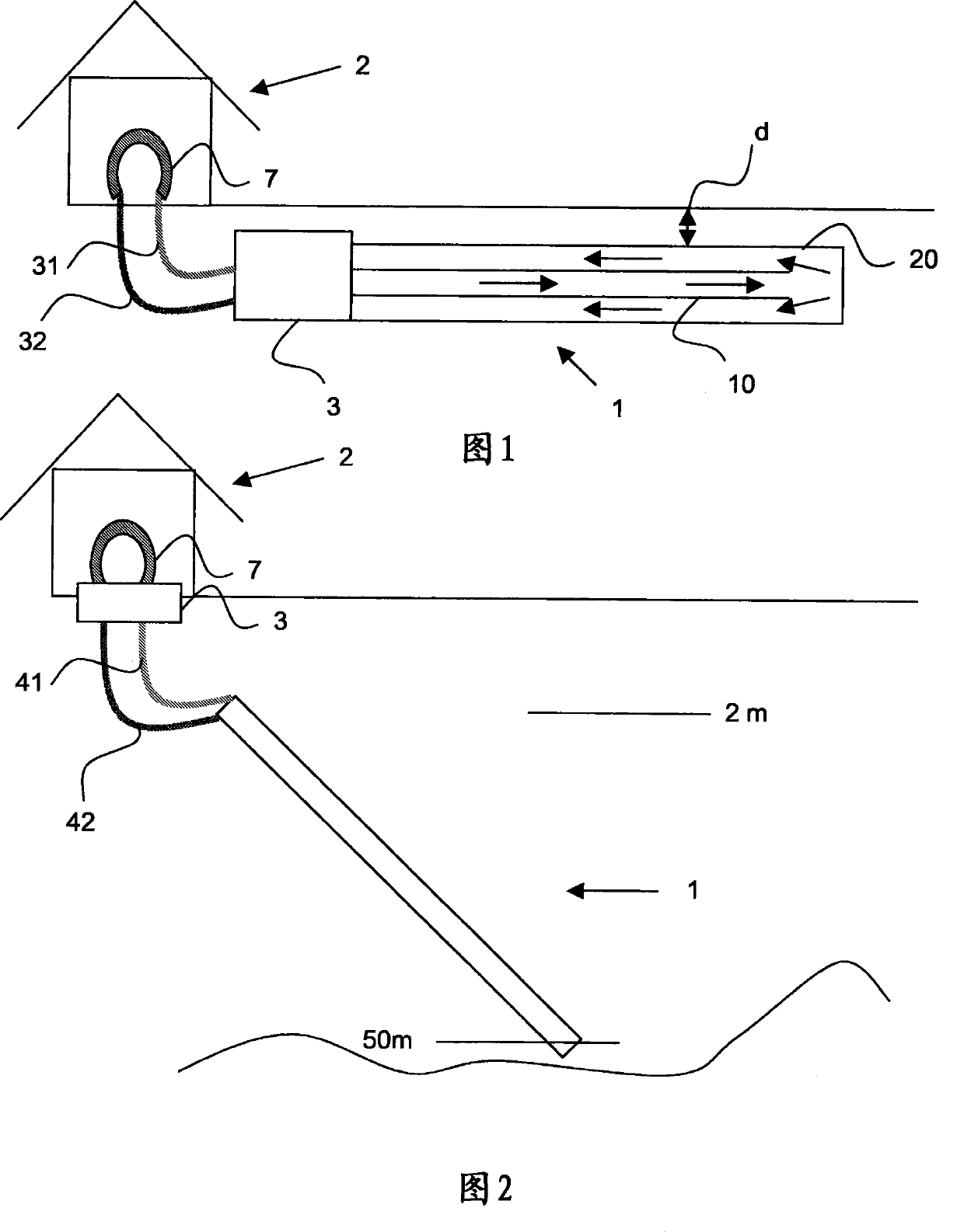
[0046] Referring to Figure 1, this figure shows an embodiment of the system according to the invention, wherein the pipeline 1 is placed horizontally below ground. The depth d of the duct may be eg 1.2 to 2 metres. The terminal 3 utilizes the low energy accumulated in the piping system 1 and transmits it through the transmission pipe 31 to the house 2 where it circulates through the heating circuit 7 and returns along the transmission pipe 32 to the collecting pipe system. Here pipe 1 is directly connected to terminal 3. Terminal 3 may be, for example, a geothermal heat pump. The figure shows a schematic diagram of a pipe 1 from which the cooled medium fluid is conveyed along an inner pipe 10 of smaller diameter. The medium moves at the outer end of the inner pipe to the outer pipe 20 , the diameter of which is greater than the diameter of the inner pipe 10 .

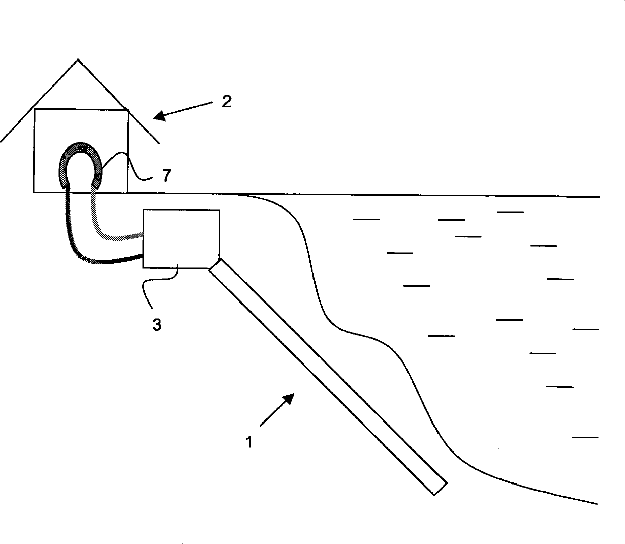
[0047] FIG. 2 shows a second embodiment of the system according to the invention, in which the pipe 1 in FIG. 1 is...


PUM


Abstract

The invention relates to a system for utilizing low energy, comprising a terminal (3), a heating circuit (7) and a ground circuit (1), whereby heat bound to a solution circulating in the ground circuit is transferred with the terminal (3), such as a ground heat pump, to the heating circuit (7). The invention is characterized in that the ground circuit (1) is implemented with an inner pipe (10) and outer pipe (20) surrounding it in such a way that the outer end of the outer pipe (20) is closed, whereby the solution can, depending on the flowing direction, move at the end of the pipe (1) from the inner pipe to the outer pipe and vice versa. Further, the invention relates to a pipe (1) for utilizing low energy.

Description

technical field [0001] The present invention relates to the utilization of low energy and more particularly to a system in which thermal energy is transferred from earth, rock or water via a medium fluid through a terminal such as a heat pump. Background technique [0002] Low energy here refers to a low temperature heat source, the temperature of which may be eg +2 to +10 degrees. In this specification, geothermal heat supplied by a heat source such as land, rock, or water is referred to as low energy. The use of low energy such as land, rock or water is generally used to heat buildings or domestic water by means of eg heat pumps or thermal energy collection circuits. This geothermal system works on a similar principle to that of a chiller, only in reverse, so for example the system cools the ground and heats the water reservoir. Typically, two to four thermal units are gained for every unit of electrical energy consumed. The utilization factor is obviously better than d...

Claims


Application Information

Patent Timeline
IPC IPC(8): F24J3/08F25B30/06F24T10/10
CPCF24J3/08Y02E10/10F24T10/10
Inventor 埃尔基-尤西·帕努拉莫里·利斯科斯基
Owner MATEVE OY
Features
  • Generate Ideas
  • Intellectual Property
  • Life Sciences
  • Materials
  • Tech Scout
  • Unparalleled Data Quality
  • Higher Quality Content
  • 60% Fewer Hallucinations
Learn More