
System and method of ct imaging with second tube/detector patching

A technology of CT imaging and detectors, which is applied in the measurement of radiation, instruments for radiological diagnosis, X/γ/cosmic radiation measurement, etc. It can solve the problems of not having data reconstruction saturation data, not including photon counting ability, etc.

Active Publication Date: 2009-03-04
GENERAL ELECTRIC CO
View PDF0 Cites 14 Cited by
  • Summary
  • Abstract
  • Description
  • Claims
  • Application Information

AI Technical Summary

Problems solved by technology

However, these systems neither include photon counting capabilities nor the ability to reconstruct (re-bin) with data from unsaturated detector subsystems or simultaneously correct saturated data in one detector subsystem

Method used


Image

  • System and method of ct imaging with second tube/detector patching
  • System and method of ct imaging with second tube/detector patching
  • System and method of ct imaging with second tube/detector patching

Examples


Embodiment Construction

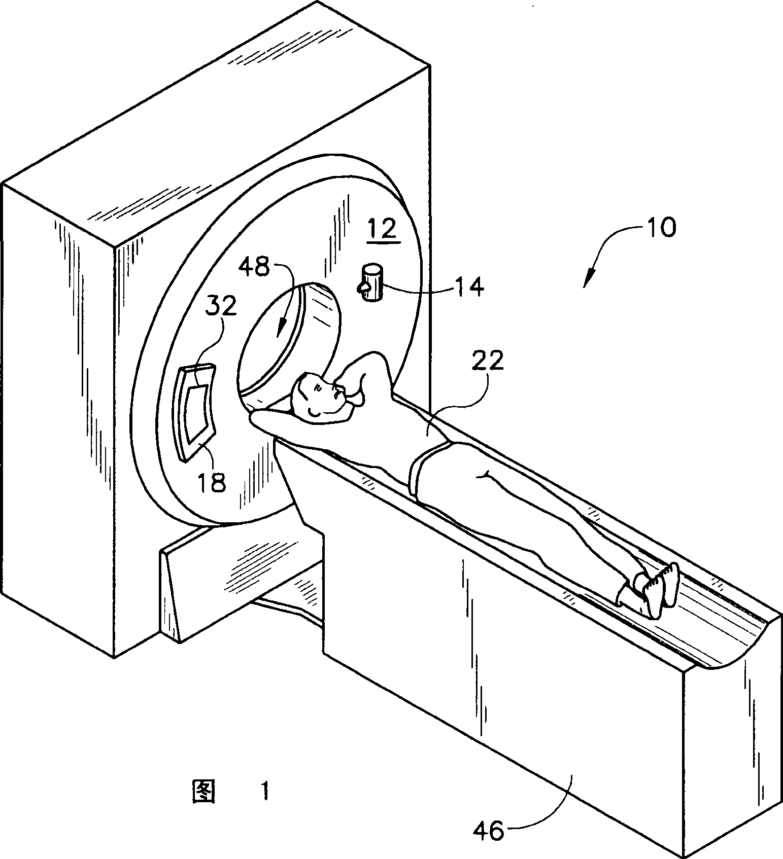
[0029] Diagnostic equipment includes x-ray systems, magnetic resonance (MR) systems, ultrasound systems, computed tomography (CT) systems, positron emission tomography (PET) systems, ultrasound, nuclear medicine, and other types of imaging systems. Applications for x-ray sources include imaging, medical examination, security, and industrial inspection applications. Here, however, those skilled in the art will see an implementation suitable for use with single-layer or other multi-layer configurations. And, an implementation that can be used to detect and convert x-rays. Those skilled in the art will further see an implementation that can be used to detect and convert other high frequency electromagnetic energies. An implementation that can be used in "third generation" CT scanners and / or other CT systems.

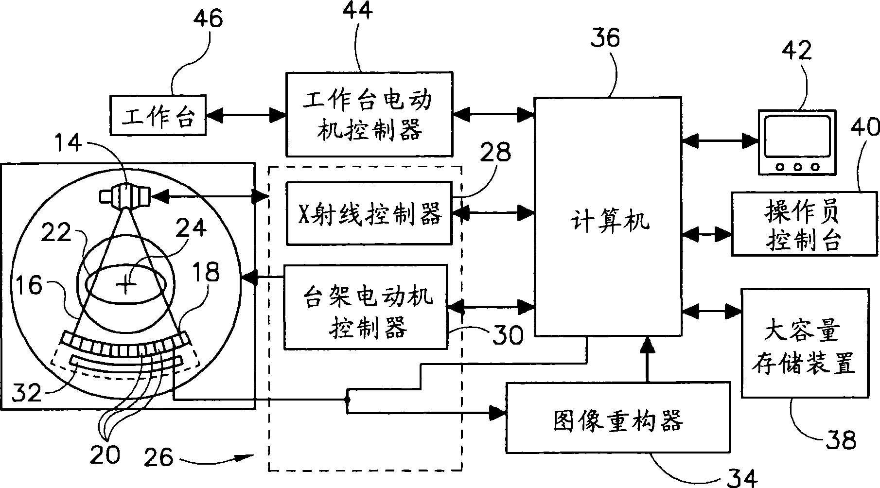
[0030] The operating environment of the present invention is described with reference to a sixty-four slice computed tomography (CT) system. However, those skilled in th...


PUM


Abstract

The present invention relates to a CT imaging system comprising a second ray tube / detector and a method thereof. The CT imaging system (10) includes a rotatable gantry (12) having an opening (48) to receive an object (22) to be scanned, a first x-ray emission source (90, 190) attached to the rotatable gantry (12) and configured to emit x-rays toward the object (22), and a second x-ray emission source (92, 192) attached to the rotatable gantry (12) and configured to emit x-rays toward the object (22). A first detector (100, 200) is configured to receive x-rays that emit from the first x-ray emission source (90, 190), and a second detector (106, 206) configured to receive x-rays that emit from the second x-ray emission source (92, 192). A first portion of the first detector (100, 200) is configured to operate in an integration mode and a first portion of the second detector (106, 220) is configured to operate in at least a photon-counting mode.

Description

technical field [0001] The present invention relates generally to diagnostic imaging, and more particularly to methods and configurable pattern detectors for correcting saturation data that occur in photon counting. Background technique [0002] Typically, in computed tomography (CT) imaging systems, an x-ray source emits a fan beam at an object or target, such as a patient or a piece of luggage. Hereinafter, the terms "object" and "target" shall include anything capable of being imaged. After being attenuated by the object, the beam of radiation strikes the radiation detector array. The intensity of the attenuated beam radiation detected at the radiator typically depends on the attenuation of the x-ray beam by the object. Each detector element in the detector array generates a separate electrical signal indicative of the attenuated beam of radiation received by each detector element. The electrical signals are sent to a data processing system for analysis, which ultimate...

Claims


Application Information

Patent Timeline
Patent Type & Authority Applications(China)
IPC IPC(8): A61B6/03G01N23/04G01T1/161
CPCG01T1/2985A61B6/032A61B6/4014A61B6/4241
Inventor J·E·特卡奇克S·K·巴苏X·吴杜岩峰
Owner GENERAL ELECTRIC CO
Learn More