
Perpendicular magnetic recording medium and magnetic recording and reproducing apparatus using the same

A perpendicular magnetic recording and reproducing device technology, applied in the directions of magnetic recording, data recording, recording information storage, etc., can solve the problems of reduced recording/reproducing characteristics, limited, increased medium noise, etc. Read signal quality, effect of high thermal agitation impedance

Inactive Publication Date: 2009-03-04
HITACHI GLOBAL STORAGE TECH NETHERLANDS BV
View PDF6 Cites 12 Cited by
  • Summary
  • Abstract
  • Description
  • Claims
  • Application Information

AI Technical Summary

Problems solved by technology

[0006] In order to increase the thermal agitation resistance of the perpendicular magnetic recording medium, it is effective to increase the magnetic anisotropy energy of the magnetic particles, but in this case the magnetic field necessary for recording is increased
On the other hand, since the recording magnetic field that can be generated from the recording head is limited when the necessary recording magnetic field is increased, recording is difficult when using a recording head that may significantly degrade the recording / reproducing characteristics
In addition, the thermal agitation resistance can also be improved by making the magnetic particles in the magnetic recording layer larger; however, in this case, the fine zigzag shape of the magnetization transition region is usually enlarged to possibly increase the media noise
[0007] As described above, the means for increasing the thermal agitation resistance are generally accompanied by a decrease in recording / reproducing characteristics in a high recording density area

Method used


Image

  • Perpendicular magnetic recording medium and magnetic recording and reproducing apparatus using the same
  • Perpendicular magnetic recording medium and magnetic recording and reproducing apparatus using the same
  • Perpendicular magnetic recording medium and magnetic recording and reproducing apparatus using the same

Examples


Embodiment 1

[0132] By the DC sputtering method using an in-line sputtering device, a multilayer thin film was formed on a clean strengthened glass substrate of the magnetic disk. As a multilayer film, first by using AlTi 50 target (the subscript values ​​show here and hereinafter the atomic % of the content of the elements in the alloy) to prepare an AlTi amorphous alloy layer with a thickness of 30 nm. Next, by using FeCo 34 Ta 10 Zr 5 target to prepare the soft magnetic amorphous film to 30nm, to prepare the antiferromagnetic coupling film to 0.5nm by using the Ru target, and again to use the FeCo 34 Ta 10 Zr 5 target to prepare the soft magnetic amorphous thin film with a thickness of 30nm to form a soft magnetic back pad layer 12 with a three-layer stacked structure. The processing gas for each of the above layers during film formation was Ar and the gas pressure was 1 Pa. In addition, sequentially under the Ar pressure of 2Pa by using NiW 8 target to prepare the NiW alloy see...

Embodiment 2

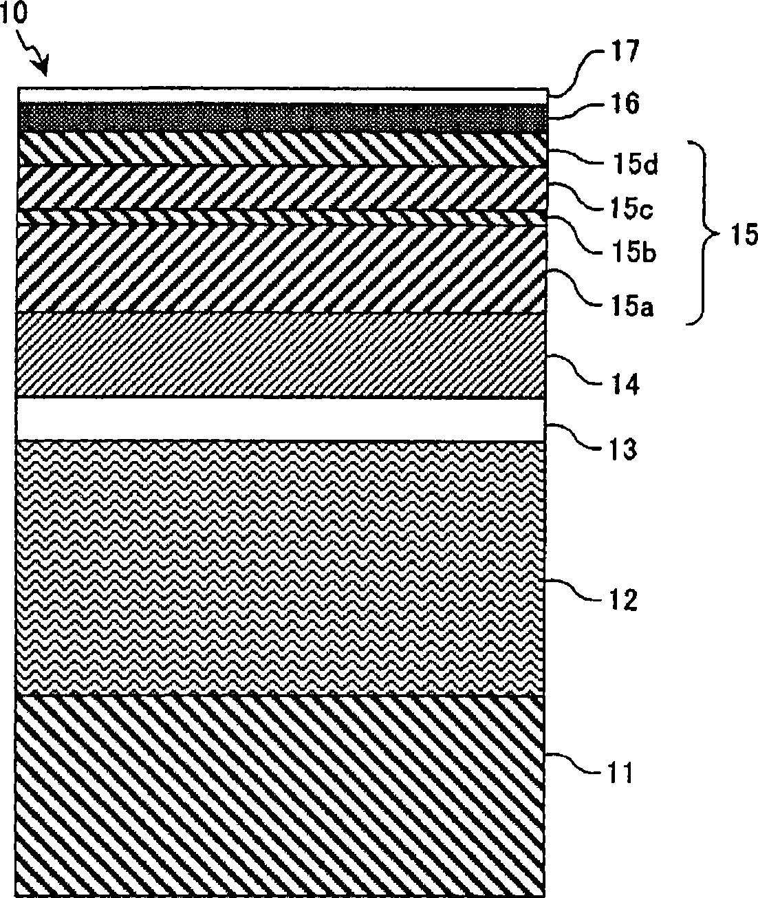
[0145] By utilizing the following with figure 1 Magnetic characteristics and recording / reproducing characteristics were measured in the same manner in the manufacturing steps and evaluation steps to manufacture perpendicular magnetic recording media. However, in Embodiment 2, the magnetic coupling layer 15b is made of CoCr having a thickness of 1.8nm 30 alloy, and the second magnetic layer 15c is made by using CoCr 17 Pt 13 -SiO 2 (8mol%) mixed target preparation. Thereafter, in Example 2, samples were fabricated while setting the sum of the thickness t2 of the second magnetic layer 15c and the thickness t3 of the third magnetic layer 15d constant and varying the ratio of t2. Figure 5A list is given of the composition, saturation magnetization Ms, and thickness of each layer constituting the magnetic recording layer of the produced perpendicular magnetic recording medium.

[0146] Figure 15 is a view showing the relationship between the ratio t2 (t2+t3) of the thicknes...

Embodiment 3

[0153] By utilizing the following with figure 1 Magnetic characteristics and recording / reproducing characteristics were measured in the same manner in the manufacturing steps and evaluation steps to manufacture perpendicular magnetic recording media. However, in Example 3, the magnetic coupling layer 15b is made of CoCr having a thickness of 1.2nm 25 Cr 10 alloy, and the second magnetic layer 15c is made by using CoCr 17 Pt 13 -SiO 2 (8mol%) mixed target preparation. Thereafter, in Embodiment 3, the thickness t2 of the second magnetic layer 15c and the thickness t3 of the third magnetic layer 15d are made the same (t2=t3), and the sum of the thicknesses of the second magnetic layer 15c and the third magnetic layer 15d ( t2+t3) were varied to form samples. Figure 6 A list is given of the composition, saturation magnetization Ms, and thickness of each layer constituting the magnetic recording layer of the produced perpendicular magnetic recording medium.

[0154] Figur...


PUM

PropertyMeasurementUnit
thicknessaaaaaaaaaa
thicknessaaaaaaaaaa
thicknessaaaaaaaaaa

Abstract

Embodiments of the present invention provide a perpendicular magnetic recording medium suitable for high density recording. According to one embodiment, a magnetic recording layer comprises four layers in which a first magnetic layer, a magnetic coupling layer, a second magnetic layer, and a third magnetic layer are formed above a substrate. The first magnetic layer and the second magnetic layer are perpendicular magnetization films containing an oxide, and ferromagnetically coupled with each other by way of the magnetic coupling layer, and they are, more preferably, a Co alloy layer containing an oxide. The third magnetic layer is ferromagnetically coupled with the second magnetic layer. The concentration of the oxide contained in the third magnetic layer is lower than the concentration of the oxide in the second recording layer, or the third magnetic layer does not contain the oxide. In this case, magnetic property is set for the anisotropic magnetic field Hk1 of the first magnetic layer and the anisotropic magnetic field Hk2 of the second magnetic layer, so as to satisfy: Hk1>Hk2.

Description

technical field [0001] The present invention relates to a perpendicular magnetic recording medium and a perpendicular magnetic recording type magnetic recording and reproducing apparatus using the same. Background technique [0002] Hard disk drives (HDDs) have become indispensable information storage devices in computers and various consumer electronics products, especially in the application of large-capacity information storage. Magnetic recording systems are basically classified into two types of technical methods based on the direction of the magnetization vector in the magnetic recording layer in the magnetic recording medium. One of the methods is longitudinal magnetic recording (LMR) and the other is perpendicular magnetic recording (PMR). In recent years, HDD recording systems have been in transition from longitudinal magnetic recording systems to perpendicular magnetic recording systems. Although the recording density obtained by the longitudinal magnetic recordi...

Claims


Application Information

Patent Timeline
Patent Type & Authority Applications(China)
IPC IPC(8): G11B5/66G11B5/65G11B5/64
CPCG11B5/65G11B5/82G11B5/66G11B5/672
Inventor 根本广明武隈育子张振刚
Owner HITACHI GLOBAL STORAGE TECH NETHERLANDS BV
Learn More