Relay flat iron core machining method and apparatus

A processing method and technology of processing device, applied in relay, inductor/transformer/magnet manufacturing, circuits, etc., can solve the problems of inability to realize automatic production, easy generation of burrs and burrs, shape limitation of cold forging parts, etc., and achieve continuous automation. The effect of producing and eliminating burrs

Active Publication Date: 2009-03-11
SHENZHEN DONGYANGWANGHE IND CO LTD
View PDF0 Cites 6 Cited by
  • Summary
  • Abstract
  • Description
  • Claims
  • Application Information

AI Technical Summary

Problems solved by technology

[0002] The existing cold forging parts processing methods basically use round bar-shaped wires to be extruded or upset by cold forging machines, such as processing cylindrical rods, screws, nuts and other parts, which will affect the shape of cold forging parts. have some restrictions
For example, a three-die three-blow cold forging machine that uses a clip conveying device to realize automatic feeding. When processing non-cylindrical parts, such as flat iron cores for relays, the semi-finished product is in the process of being conveyed. There will be rotation, so that the semi-finished product formed by the first main mold cannot be transported stably into the second main mold, so that automatic production cannot be realized
In addition, the molds of the first main mold, the second main mold and the third main mold must be assembled on the cold forging machine. When assembling, it is necessary to ensure that after the assembly of the three molds, their centerlines are on the same horizontal plane. It is difficult to find the benchmark for the die assembly and fixing method of the cold forging machine
In addition, for the upsetting of non-circular heads, such as: square, hexagonal and semicircular, etc., it is easy to produce burrs and burrs on the edges, which is a fatal defect for the relay core. Because after the relay iron core is assembled and riveted, if there is iron chipping, burr sticking or falling off, it will affect the sensitivity of the relay or even short circuit
If it is used in important equipment such as cars, the consequences will be very serious

Method used


Image

  • Relay flat iron core machining method and apparatus
  • Relay flat iron core machining method and apparatus
  • Relay flat iron core machining method and apparatus

Examples


Embodiment Construction

[0030] The specific embodiment of the processing method of relay flat iron core of the present invention is to utilize three-die three-blow cold forging to process relay flat iron core, comprising the following steps:

[0031] (S1) After the flat wire rod is cut into a blank of a certain length in the cutting fixed die, it is poked out by a thimble, and then the blank is transported to the cavity entrance of the first main mold by the first conveying clip;

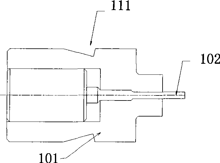
[0032] (S2) The punching needle of the first die pushes the blank into the first main die and extrudes one end of the billet, then the semi-finished product is ejected by the ejector pin of the first main die, and the semi-finished product is transported to the second main die by the second transfer clamp The cavity entrance of the mold;

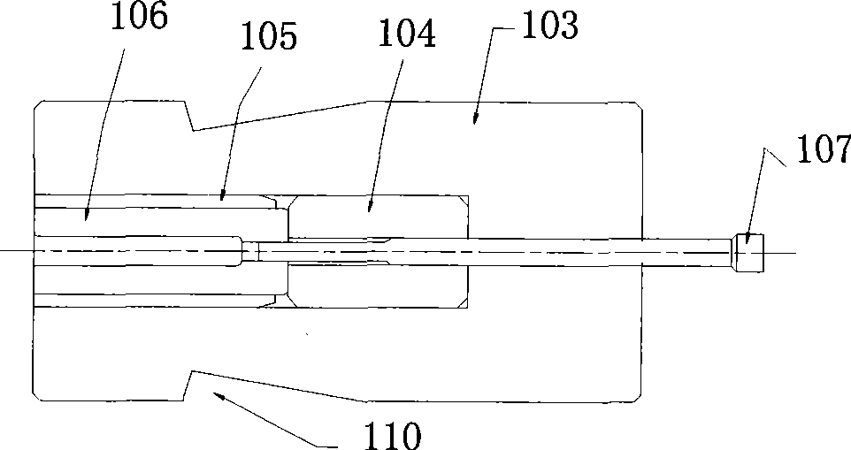
[0033] (S3) The punch pin of the second die pushes the semi-finished product into the second main mold and upsets the other end of the semi-finished product, and then the semi-finished p...


PUM


Abstract

The invention relates to a relay flat iron core processing method and a device thereof. The method comprises the steps: the relay flat iron core is cold-forged by three moulds and three strokes, a flat wire is cut into a proper length in a cutting fixing mould, and then the iron core is moulded in the three main moulds. The device comprises a fixing and cutting mould which is used for cutting the flat wire, the three main moulds, three punching moulds and a removing clamp with a U-shaped groove, wherein the three main moulds and the three punching moulds are used for cold-forging and moulding the flat wire. The relay flat iron core processing method and the device enable the flat wire to be moulded in a sealing mold cavity and eliminate the defect that the head of a square part is easy to generate fuzzy grains when being upset, and meanwhile, the automation continuous production can be realized.

Description

technical field [0001] The invention relates to cold forging, and more specifically relates to a method and device for processing flat iron cores of relays. Background technique [0002] The existing cold forging parts processing methods basically use round bar-shaped wires to be extruded or upset by cold forging machines, such as processing cylindrical rods, screws, nuts and other parts, which will affect the shape of cold forging parts. There are some restrictions. For example, a three-die three-blow cold forging machine that uses a clip conveying device to realize automatic feeding. When processing non-cylindrical parts, such as flat iron cores for relays, the semi-finished product is in the process of being conveyed. Rotation will occur, so that the semi-finished product formed by the first main mold cannot be transported into the second main mold stably, so that automatic production cannot be realized. In addition, the molds of the first main mold, the second main mol...

Claims


Application Information

Patent Timeline
Patent Type & Authority Applications(China)
IPC IPC(8): H01H49/00H01F3/00H01F41/02
Inventor 滨中精一汪永枝陈立华
Owner SHENZHEN DONGYANGWANGHE IND CO LTD
Why Eureka
Try Eureka