U shaped beam three-face punching technique and production device using the technique

A production equipment and punching technology, applied in the field of "U"-shaped beam punching process, can solve the problems of low handling and turning efficiency, large mechanical area, and low production efficiency, etc. The effect of small area and improved production efficiency

Inactive Publication Date: 2009-03-18
JINAN CASTING FORGING MACHINERY INST
View PDF0 Cites 28 Cited by
  • Summary
  • Abstract
  • Description
  • Claims
  • Application Information

AI Technical Summary

Problems solved by technology

This production process uses more punching machines. Although the positioning is more accurate, there are problems such as low production efficiency and complicated process.
At the same time, the existing "U"-shaped beam punching process adopts manual handling or mechanical and manual handling during the process of "U"-shaped beam handling and turning. The handling and turning efficiency is low, and the corresponding professional machinery occupies a large area, resulting in Reduced production efficiency and potential safety hazards

Method used


Image

  • U shaped beam three-face punching technique and production device using the technique
  • U shaped beam three-face punching technique and production device using the technique
  • U shaped beam three-face punching technique and production device using the technique

Examples


Embodiment Construction

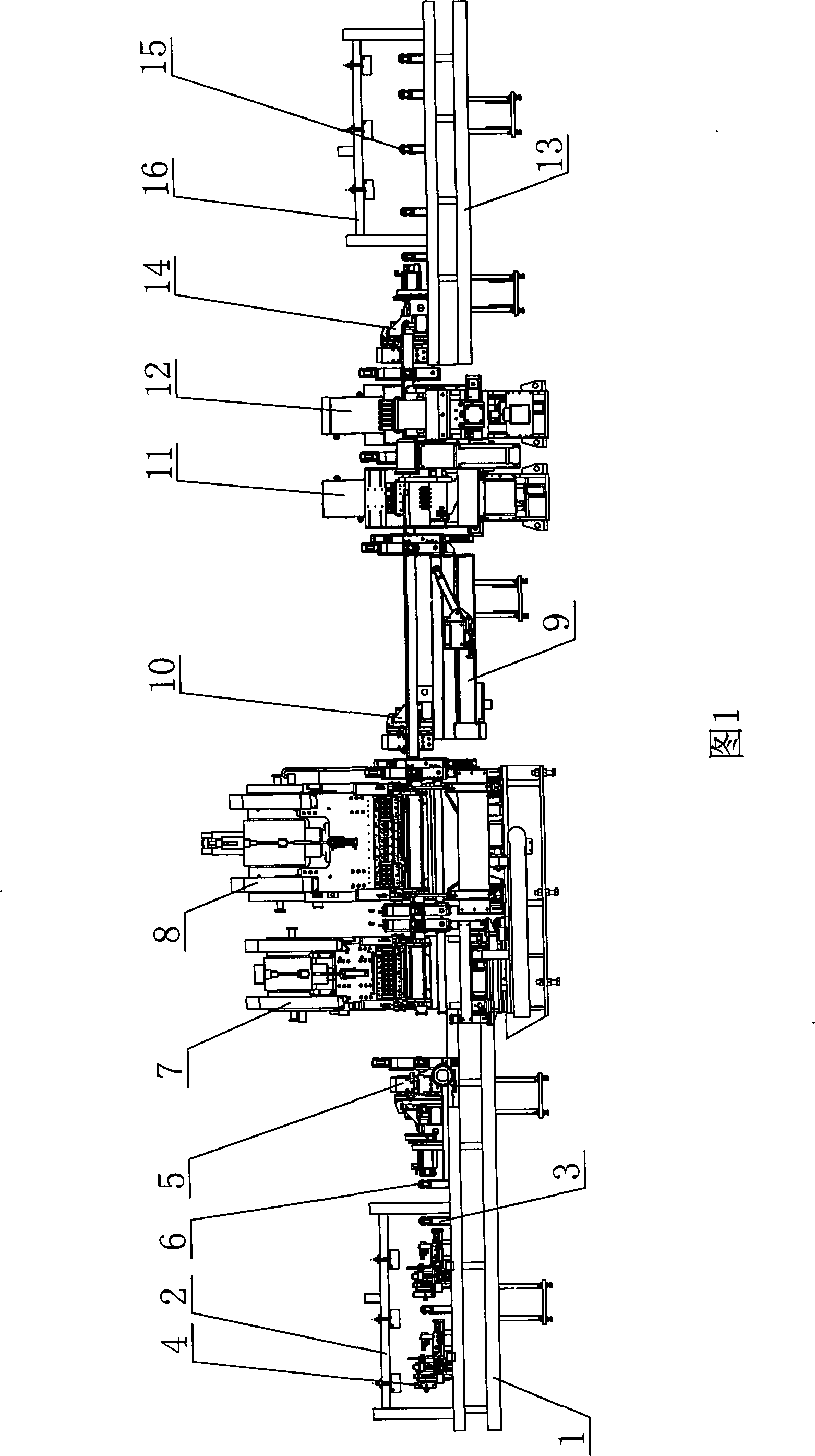
[0020] A kind of " U " shaped beam three-sided punching process of the present invention, its technological process is:

[0021] (1) Place the "U" shaped beam on the loading platform for standby;

[0022] (2) Use the feeding extraction device to suck up the spare "U"-shaped beams in sequence. For the "U"-shaped beams with the opening upwards, they are first hoisted to the automatic turning device, and then placed on the feeding end for support after being automatically turned 180° On the rollers, the "U" shaped beam with the opening downwards is directly hoisted to the supporting rollers at the feeding end;

[0023] (3) The supporting rollers support the "U" beam, and push the "U" beam to the reference positioning roller for positioning;

[0024] (4) Use the first feeding and clamping device to clamp the "U"-shaped beam web, and send it to the small abdominal punching machine that can move the X / Y axis and the large abdominal punching machine that can move the Y axis. on sta...


PUM


Abstract

The invention discloses a three-side-punch process of a U-shaped beam and a production device used in the process. The process comprises the following steps: the U-shaped beams are placed on a feeding platform, a feed picking device is adopted to successively pick up the spare U-shaped beams and hoist the beams to a support roller of the feeding end; a first feeding clamping device is adopted to clamp the U-shaped webs and feed the webs to working platforms of a ventral small punching machine which can move along the X / Y axis and a ventral large punching machine which can move along the Y axis; the ventral small punching machine which can move along the X / Y axis and the ventral large punching machine which can move along the Y axis punch the beams; a second feeding clamping device clamps the U-shaped beams and continuously feed the beams to the working platform of a left wing punching machine and a right wing punching machine; the left wing punching machine and the right wing punching machine punch the beams; the U-shaped beams are hoisted to a discharging platform after being fully punched. The invention has the advantages of simple process, high production efficiency, low cost and reasonable process arrangement; and the produced U-shaped beams have precise punching location.

Description

technical field [0001] The invention relates to the field of "U"-shaped beam punching technology, in particular to a "U"-shaped beam three-side punching technology and production equipment used therefor. Background technique [0002] At present, in the field of "U"-shaped beam punching technology, manufacturers use five punching machines for punching, namely: the first small punching machine for the ventral surface, the large punching machine for the ventral surface, and the second small punching machine for the ventral surface machine, left wing puncher and right wing puncher. This production process uses many punching machines. Although the positioning is relatively accurate, there are problems such as low production efficiency and complicated process. At the same time, the existing "U"-shaped beam punching process adopts manual handling or mechanical and manual handling during the process of "U"-shaped beam handling and turning. The handling and turning efficiency is low...

Claims


Application Information

Patent Timeline
Patent Type & Authority Applications(China)
IPC IPC(8): B21D28/32B21D43/00B21D28/34B21D37/10
Inventor 刘振堂赵加蓉何梦辉韩学军李永刚王传标李大鹏李耶夫栾红霞
Owner JINAN CASTING FORGING MACHINERY INST
Why Eureka
Try Eureka