Stamping processing equipment for automobile aluminum pieces

A technology for stamping and aluminum parts, which is applied in the field of stamping and processing equipment for automobile aluminum parts, can solve the problems of irregular shape of aluminum parts, reduce production efficiency, affect punching quality, etc., achieve stable punching action, avoid drill bit damage, The effect of avoiding the deviation of the punching position

Inactive Publication Date: 2018-08-21
芜湖同创模具机械有限公司
View PDF6 Cites 2 Cited by
  • Summary
  • Abstract
  • Description
  • Claims
  • Application Information

AI Technical Summary

Problems solved by technology

[0002] Most of the existing automotive aluminum parts are formed by stamping first, and then the stamped aluminum parts are taken out and drilled. In this way, the aluminum parts are processed to make the processing process of the aluminum parts clear. However, after the aluminum parts are stamped and formed, It needs to be clamped and stabilized again on the drilling rig equipment, and the drill bit must be aligned with the drilling station before the drilling operation can be carried out, which greatly reduces the production efficiency; moreover, the shape of the aluminum parts after stamping is irregular, and it is difficult to effectively Fixed, the workpiece is prone to shake during the drilling process, resulting in large errors and affecting the drilling quality

Method used


Image

  • Stamping processing equipment for automobile aluminum pieces
  • Stamping processing equipment for automobile aluminum pieces

Examples


Embodiment Construction

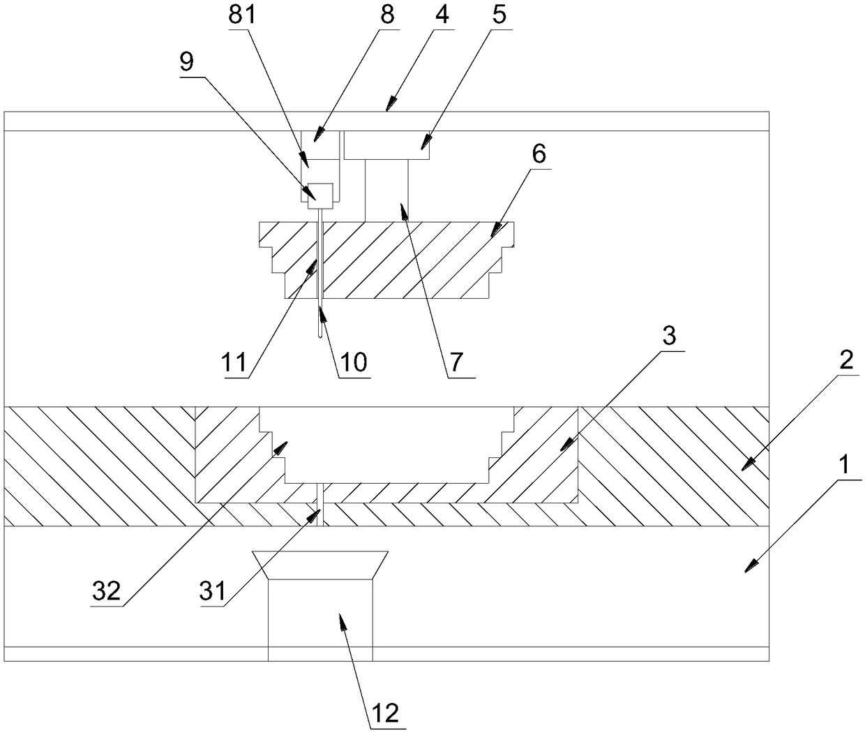
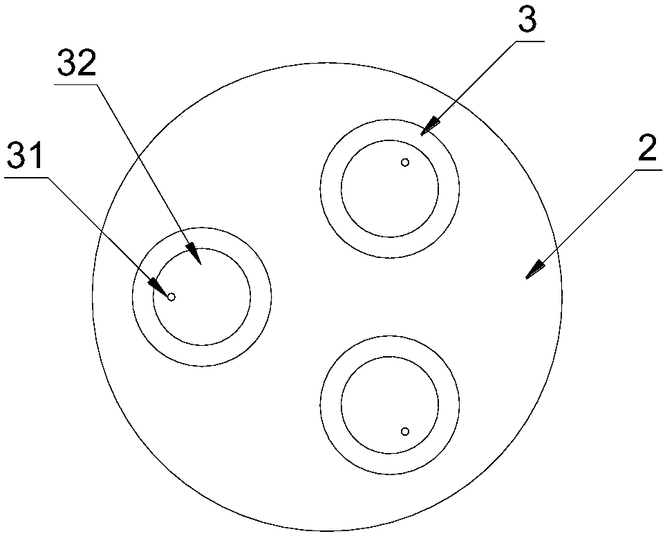
[0019] Such as figure 1 as shown, figure 1 It is a structural schematic diagram of a stamping processing equipment for aluminum parts of automobiles proposed by the present invention; figure 2 It is a partial structural schematic diagram of the stamping processing equipment for automobile aluminum parts proposed by the present invention.

[0020] refer to figure 1 , a stamping processing equipment for automobile aluminum parts proposed by the present invention, including a base 1, a workbench 2, a mold 3, a first driving mechanism 5, a first telescopic rod 7, a stamping head 6, a second driving mechanism 8, a second telescopic Rod 81, drilling machine 9, drill bit 10 and frame 4;

[0021] The workbench 2 is set on the base 1, and a placement groove is arranged on the workbench 2; the mold 3 is fixed in the placement groove; the mold 3 is provided with a cavity 31, and the bottom of the cavity 31 is provided with a discharge hole for the drill bit 10 to pass through vertica...


PUM


Abstract

The invention discloses stamping processing equipment for automobile aluminum pieces. The stamping processing equipment comprises a base, a workbench, a mold, a first driving mechanism, a first telescopic rod, a stamping head, a second driving mechanism, a second telescopic rod, a drilling machine, a drilling bit and a rack, wherein the workbench is arranged on the base, and a placing groove is formed in the workbench; the mold is fixed in the placing groove; the mold is provided with a cavity, and a relief hole is formed in the bottom of the cavity; the first driving mechanism and the seconddriving mechanism are arranged on the rack side by side; the upper end of the first telescopic rod is connected to the first driving mechanism, and the lower end of the first telescopic rod is connected to the stamping head; the upper end of the second telescopic rod is connected to the second driving mechanism, and the lower end of the second telescopic rod is connected to the drilling machine; the drilling bit is vertically installed at the bottom of the drilling machine, and a through hole is formed in the stamping head. In the stamping processing equipment, after punch forming of workpieces, perforation is carried out on the workpieces directly, the workpieces are clamped stably, the perforation quality is high, and the work efficiency is high.

Description

technical field [0001] The invention relates to the field of stamping equipment, in particular to stamping processing equipment for aluminum parts of automobiles. Background technique [0002] Most of the existing automotive aluminum parts are formed by stamping first, and then the stamped aluminum parts are taken out and drilled. In this way, the aluminum parts are processed to make the processing process of the aluminum parts clear. However, after the aluminum parts are stamped and formed, It needs to be clamped and stabilized again on the drilling rig equipment, and the drill bit must be aligned with the drilling station before the drilling operation can be carried out, which greatly reduces the production efficiency; moreover, the shape of the aluminum parts after stamping is irregular, and it is difficult to effectively Fixed, the workpiece is prone to shake during the drilling process, resulting in large errors and affecting the drilling quality. Contents of the inve...

Claims


Application Information

Patent Timeline
Patent Type & Authority Applications(China)
IPC IPC(8): B23P23/04B23Q11/00
CPCB23P23/04B23Q11/0042
Inventor 陶文
Owner 芜湖同创模具机械有限公司
Why Eureka
Try Eureka