Optical fiber repeater, time delay measurement method, device thereof, and compensation method, system

A technology of optical fiber repeater and delay measurement, which is applied in the field of communication, can solve the problems of difficult alignment of baseband signal delay, difficulty of coordination and stable operation of optical fiber repeater, and achieve the effect of delay

Inactive Publication Date: 2009-03-18
SHENZHEN GRENTECH CO LTD
View PDF0 Cites 18 Cited by
  • Summary
  • Abstract
  • Description
  • Claims
  • Application Information

AI Technical Summary

Problems solved by technology

[0006] The purpose of the present invention is to provide a method for measuring the time delay of an optical fiber repeater, which aims to solve the problem of the existing technology in the optical fiber repeater caused by the difficulty in aligning the time delay of the baseband signals of the multi-level coverage end equipment in the optical fiber repeater. Difficult to coordinate and work stably

Method used


Image

  • Optical fiber repeater, time delay measurement method, device thereof, and compensation method, system
  • Optical fiber repeater, time delay measurement method, device thereof, and compensation method, system
  • Optical fiber repeater, time delay measurement method, device thereof, and compensation method, system

Examples


Embodiment Construction

[0036] In order to make the object, technical solution and advantages of the present invention clearer, the present invention will be further described in detail below in conjunction with the accompanying drawings and embodiments. It should be understood that the specific embodiments described here are only used to explain the present invention, not to limit the present invention.

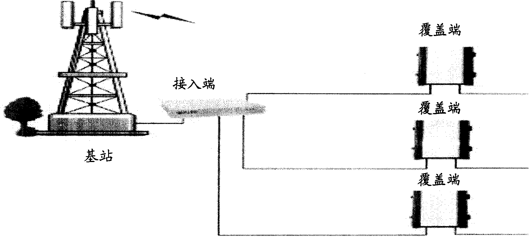
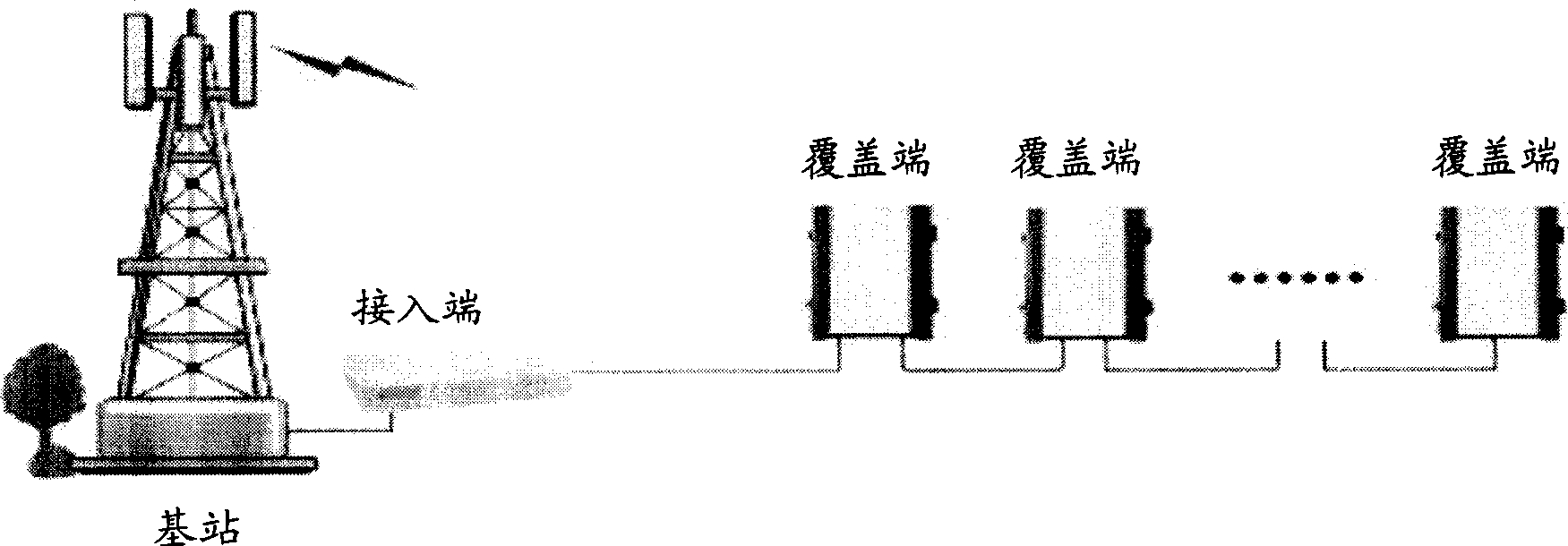
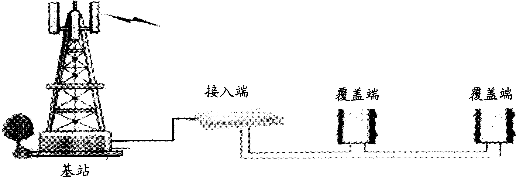
[0037] In the embodiment of the present invention, the central office equipment REC sends delay test instructions to each level of coverage end equipment RE in the first N-1 level of coverage equipment RE in the cascade, and the first N-1 level of coverage end equipment in the cascade connection Each level of coverage end equipment RE in the RE respectively tests the single-line transmission delay of the fiber link between itself and the next level of coverage end equipment RE according to the delay test command. The sum of the single-line transmission delay obtained by the first-level coverage end...


PUM


Abstract

The invention is appropriate for the communication filed, which provides a fiber optic repeater, a time delay measurement method and a device for the same. The method comprises the steps below: the capped end equipment of each level in local equipment forward N-1 level capped end sends a time delay test instruction respectively; the capped end equipment of each level that receives the time delay test instruction tests this level single transmission time delay of the optic fiber link between itself and next-level capped end equipment; the local end equipment acquires the single line transmission time delay of the optic fiber link between the local end equipment and the N-level capped end equipment, according to the sum of this level single line transmission time delay acquired by each level capped end equipment in the former N-1 level capped end equipment, to compensate base band signal time delay of the former N-1 level capped end with reference on the single line transmission time delay. The embodiment of the invention implements the situation below: when multi-level capped end equipment is concatenated in the fiber optic repeater, the up / down link base band I / O signal time delay of all the capped end equipment is aligned automatically, so that the fiber optic repeater can work coordinately and stably.

Description

technical field [0001] The invention belongs to the communication field, and in particular relates to an optical fiber repeater, a time delay measurement method and device thereof, and a time delay compensation method and system. Background technique [0002] According to different transmission forms, repeaters can generally be divided into wireless repeaters, optical fiber repeaters and microwave repeaters. Among them, the optical fiber repeater uses optical cable as the transmission medium, so that it is not limited by isolation, signal source and installation conditions, and has many advantages such as system stability, flexible antenna selection, and convenient installation, which makes the application of optical fiber repeater more and more more extensive. [0003] The optical fiber repeater generally includes an optical near-end unit and an optical remote unit connected to the optical near-end unit through optical fibers. It can generally adopt three networking modes:...

Claims


Application Information

Patent Timeline
IPC IPC(8): H04Q7/30H04B7/14H04Q7/34H04B17/00H04B17/309
Inventor 陆开怀李军吴中汉
Owner SHENZHEN GRENTECH CO LTD
Why Eureka
Try Eureka