
Charge air cooler arrangement with cooler bypass and method

A configuration structure, intercooler technology, applied in the direction of machines/engines, adding non-fuel substances to fuel, charging systems, etc., can solve problems such as condensation that has not been completely solved

Inactive Publication Date: 2009-03-18
MACK TRUCKS
View PDF0 Cites 35 Cited by
  • Summary
  • Abstract
  • Description
  • Claims
  • Application Information

AI Technical Summary

Problems solved by technology

However, when only a portion of the charge air bypasses the CAC 4, even the mixture of the charge air that has bypassed the CAC and the charge air that has passed through the CAC can be at a temperature above the dew point, as Figure 1B Seen at point A in the graph of , but the charge air passing through the CAC may still be cooled to a temperature below the dew point, as seen at point B
Therefore, CAC bypass 10 does not completely solve the problem of condensation

Method used


Image

  • Charge air cooler arrangement with cooler bypass and method
  • Charge air cooler arrangement with cooler bypass and method
  • Charge air cooler arrangement with cooler bypass and method

Examples


Embodiment Construction

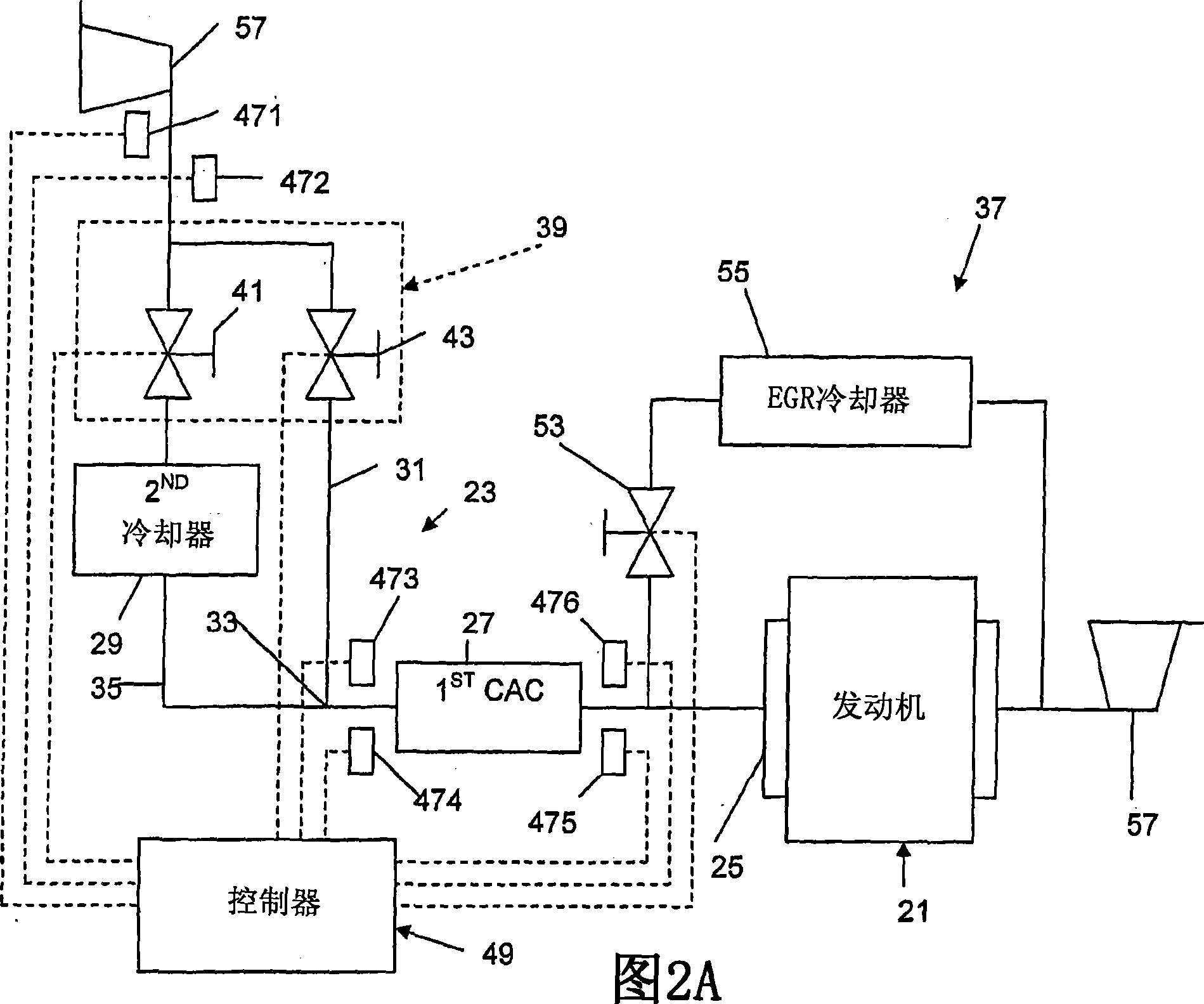
[0014] An engine 21 with an intercooler arrangement 23 is shown in FIG. 2A . An intake port, typically an intake manifold 25 , leads to the engine 21 . A first intercooler 27 (CAC) is provided upstream of the intake manifold 25 . The first CAC 27 may be less efficient than a CAC typically used in conventional internal combustion engines. More particularly, it is desirable for air located in or downstream of the first CAC that the first CAC 27 is not sufficiently effective to cool the air below the dew point within the range of temperatures and relative humidity at which it is desired to operate the engine 21 . In other words, the first CAC 27 will generally not be able to cause condensation downstream of the first CAC.

[0015] The second cooler 29 is provided upstream of the first CAC 27 . The second cooler 29 and the first CAC 27, desirably operating in series, are capable of reducing the intake air temperature over the range of temperatures and relative humidity at which...


PUM


Abstract

A charge air cooler arrangement includes a first charge air cooler disposed upstream of an engine inlet, a second cooler disposed upstream of the first charge air cooler, and a bypass line for bypassing the second cooler, a downstream end of the bypass line being disposed upstream of the first charge air cooler. A method of reducing condensation in an engine having charge air cooling is also disclosed.

Description

technical field [0001] The present invention relates to an intercooler arrangement, and more particularly, to an intercooler arrangement having a cooler bypass line. Background technique [0002] As seen in Figure 1A, which shows a conventional internal combustion engine 1, a turbocharger or supercharger 2 compresses incoming air causing it to be heated. Because hot air is less dense than cool air at the same pressure, less total air is delivered to the cylinders than it could possibly be. By cooling the intake air after compression using a device such as a charge air cooler (CAC)4 or an intercooler in a multi-stage turbo system, more intake air can be delivered to improve power. Additionally, devices such as CACs and intercoolers help increase the total boost allowed before knocking begins in the cylinders by reducing the temperature of the intake air. [0003] Exhaust gas recirculation (EGR) is a NOx (nitrogen oxides and nitrogen dioxide) reduction technology used in mo...

Claims


Application Information

Patent Timeline
IPC IPC(8): F02B33/00
CPCY02T10/146F02M25/0754F02B37/013F02B29/0412F02M25/0755F02M25/0727F02M25/0707F02B29/0418F02B29/0493F02M26/05F02M26/23F02M26/46F02M26/47Y02T10/12
Inventor 太春托德·科林·雷佩特
Owner MACK TRUCKS
Features
  • Generate Ideas
  • Intellectual Property
  • Life Sciences
  • Materials
  • Tech Scout
  • Unparalleled Data Quality
  • Higher Quality Content
  • 60% Fewer Hallucinations
Learn More