
Intercooler Having Condensate Reservoir

Inactive Publication Date: 2011-05-12
GM GLOBAL TECH OPERATIONS LLC
View PDF2 Cites 42 Cited by
  • Summary
  • Abstract
  • Description
  • Claims
  • Application Information

AI Technical Summary

Benefits of technology

[0008]An advantage of an embodiment is that a remote coolant reservoir allows for improved intercooler performance, especially when operating the vehicle in wet conditions. The condensate can be stored and fed into the engine in a controlled rate while still allowing for maximum charge-air-cooler heat exchanger effectiveness within the packaging space allowed for the heat exchanger by allowing for maximizing the frontal area in the CAC heat exchanger. Maximizing the frontal area in this way reduces the air flow restriction and reduces the pressure drop, which leads to the improved overall cooling of the charge air. This may allow for improved horsepower and torque output from the engine. Moreover, the remote coolant reservoir allows for more flexibility in the size and shape of the reservoir to provide the desired storage capacity for the condensate without reducing the cooling effectiveness of the charge air cooler heat exchanger and while providing more packaging flexibility in locating the reservoir.
[0009]Another advantage of an embodiment is that the remote condensate reservoir allows the vehicle to travel for longer periods of time without ingestion of condensate in the engine creating a significant engine misfire concern, even with an intercooled, high base boost turbocharger system. The ingestion of the condensate into the engine may be maintained at desired controlled rates, with the relatively higher pressure at a condensate drain tube and the relatively lower pressure at an intake duct connector causing a flow through the remote condensate reservoir that will draw condensate into the air stream.
[0010]Another advantage of an embodiment is that the condensate does not have to be released to atmosphere, thus avoiding concerns with vehicle emissions requirements.
[0011]Still another advantage of an embodiment is that the condensate reservoir, condensate drain tube and reservoir outlet hose do not require any moving parts, thus reducing concerns with reliability and making the assembly simple to fabricate and assemble and easy to service.

Problems solved by technology

The collected condensate can be ingested into the engine at too high of a rate, causing engine misfire.
If the misfire is severe enough, the vehicle's engine control module may light the “service engine soon” light, which is undesirable.
Moreover, the driver may also notice poor vehicle performance or rough acceleration, which are also undesirable.
However, this increases the undesirable turbo-lag that base boost is meant to minimize in the first place.
Another possibility to deal with the condensate is to use engine vacuum to extract condensate, but this may create powertrain integration concerns.
Also, another way is to allow the condensate to leak to atmosphere; however, this may be undesirable when attempting to meet certain vehicle emissions requirements.

Method used


Image

  • Intercooler Having Condensate Reservoir
  • Intercooler Having Condensate Reservoir
  • Intercooler Having Condensate Reservoir

Examples


Embodiment Construction

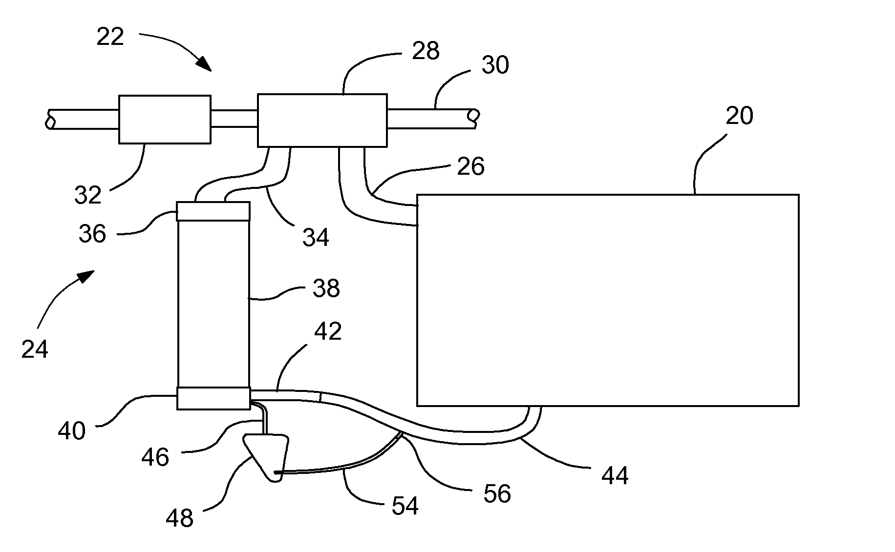
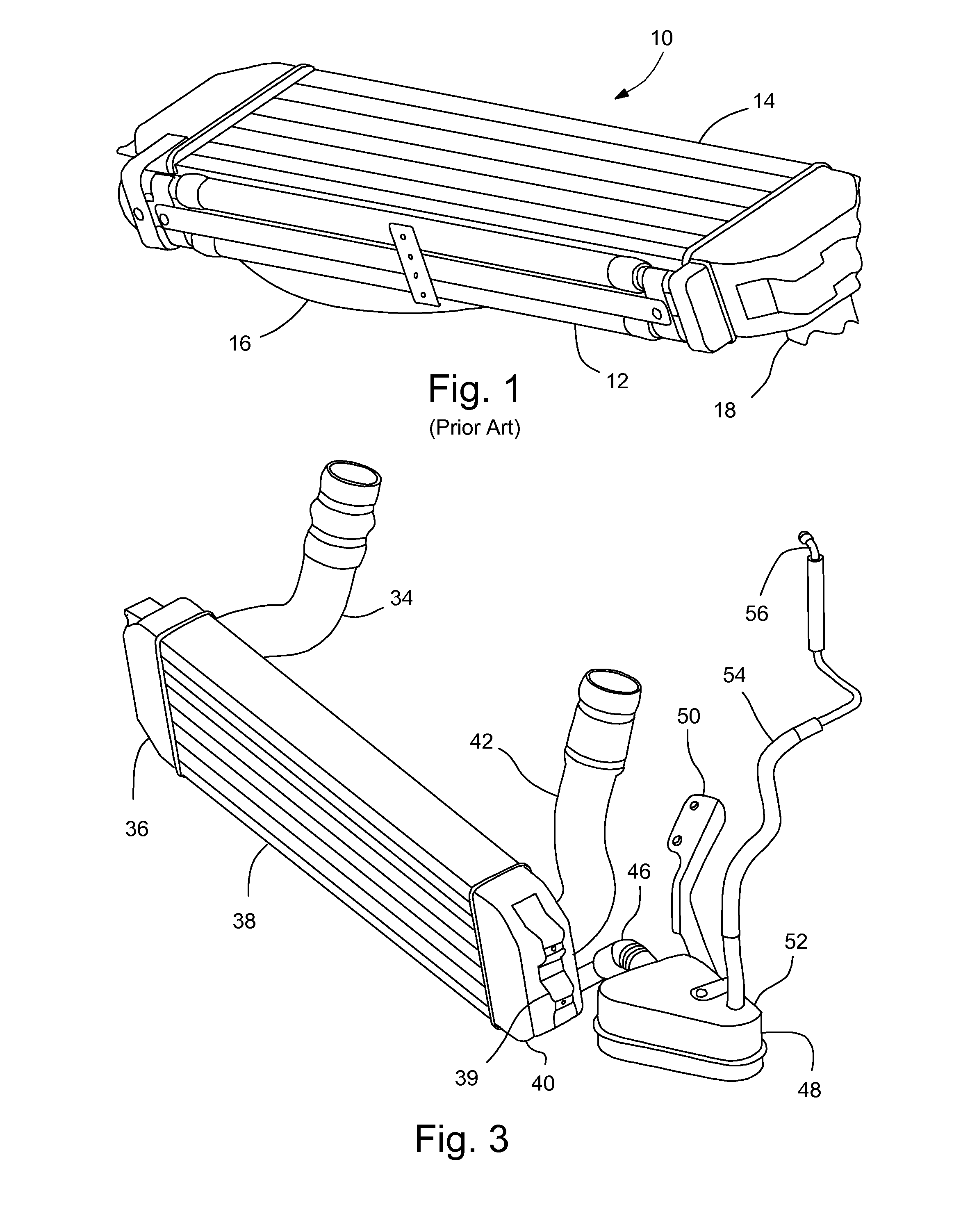
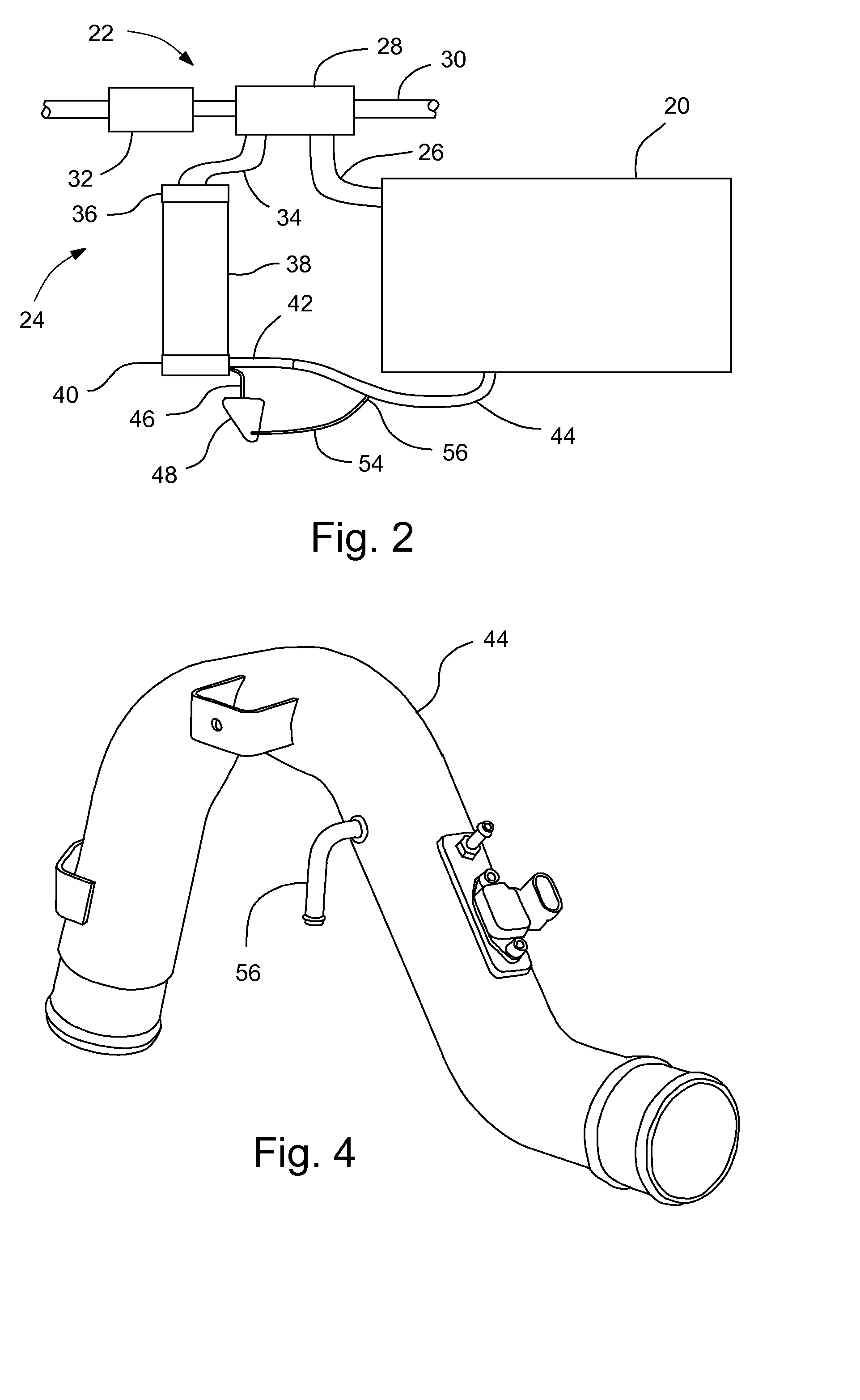
[0017]FIGS. 2-5 illustrate portions of an engine 20 and engine air intake system 22 that is employed with a vehicle. The engine air intake system 22 includes a turbocharger system 24 that compresses and cools intake air before being delivered to the engine 20. The engine 20 connects to an exhaust pipe 26 leading to a turbocharger 28 that is driven by the flow of exhaust gas from the pipe 26. An exhaust outlet of the turbocharger 28 directs air into a vehicle exhaust pipe 30. Intake air is directed through an air cleaner 32 to the turbocharger 28, which directs the charged air into an intercooler inlet tube 34.

[0018]The intercooler inlet tube 34 directs compressed air into an intake end 36 of a charge-air-cooler (CAC) heat exchanger 38 that cools the charged air. The CAC heat exchanger 38 may include mounting brackets 39 for mounting the heat exchanger in a condenser, radiator, fan module. An outlet end 40 of the CAC heat exchanger 38 directs the compressed, cooled air into an interc...


PUM


Abstract

An engine air intake system for a vehicle having an internal combustion engine may include a turbocharger; a CAC heat exchanger having an inlet end for receiving compressed intake air from the turbocharger and an outlet end; a remote condensate reservoir spaced from the CAC heat exchanger, for storing condensate therein; a condensate drain tube extending from the outlet end to the remote condensate reservoir to allow condensate produced in the CAC heat exchanger to flow into the remote condensate reservoir; an air duct connecting the outlet end to the engine to direct air flow from the outlet end to the engine; and a reservoir outlet hose connected to the remote condensate reservoir at a first end and connected to the air duct at a second end to allow condensate evaporating from the remote condensate reservoir to flow through the reservoir outlet hose into the air duct.

Description

BACKGROUND OF INVENTION[0001]The present invention relates generally to turbocharger systems used with internal combustion engines in vehicles, and more particularly to intercooler assemblies used with turbocharger systems in vehicles.[0002]Many high output turbocharged engines used in vehicles employ a base boost at relatively low engine speeds, such as during steady state highway driving. This base boost is essentially an always-on turbo boost and helps reduce turbo lag, which is a common complaint for older turbocharged engines on vehicles. A high level of base boost, together with a high thermal efficiency charge-air-cooler (CAC) heat exchanger (i.e., an intercooler), can cause condensation to form inside the CAC. This condensation typically occurs during steady state driving when ambient conditions are warm with humidity levels near one hundred percent. Such a condition may occur for an automotive vehicle during steady state highway driving in the rain.[0003]The concern with fo...

Claims


Application Information

Patent Timeline
IPC IPC(8): F02B29/04
CPCF02B29/0468F02B37/00F02M25/0222Y02T10/146F02M25/028Y02T10/121Y02T10/12
Inventor QUINN, RICHARD D.HELTON, BRANDON S.MURPHY, KENNETH J.TRAN, TUAN A.WALLA, LAWRENCE E.
Owner GM GLOBAL TECH OPERATIONS LLC
Learn More