Cooling System for Construction Machine

a construction machine and cooling system technology, applied in the direction of positive displacement liquid engines, fluid couplings, instruments, etc., can solve the problems of overcooling of the cooling water for the radiator and the working oil for the oil cooler, and longer warm-up time, so as to reduce the noise of the cooling fan and reliably produce the cooling air

Active Publication Date: 2009-09-03
NIHON KENKI CO LTD
View PDF7 Cites 42 Cited by
  • Summary
  • Abstract
  • Description
  • Claims
  • Application Information

AI Technical Summary

Benefits of technology

[0021]According to the present invention, it is possible to reduce noise of the cooling fan and to reliably produce the cooling air at a required flow rate.

Problems solved by technology

Therefore, it may occur sometimes that the cooling water for the radiator and the working oil for the oil cooler are overcooled and a longer time is taken for warm-up operation.

Method used


Image

  • Cooling System for Construction Machine
  • Cooling System for Construction Machine
  • Cooling System for Construction Machine

Examples


first embodiment

[0063]the present invention will be described below with reference to FIGS. 1-6.

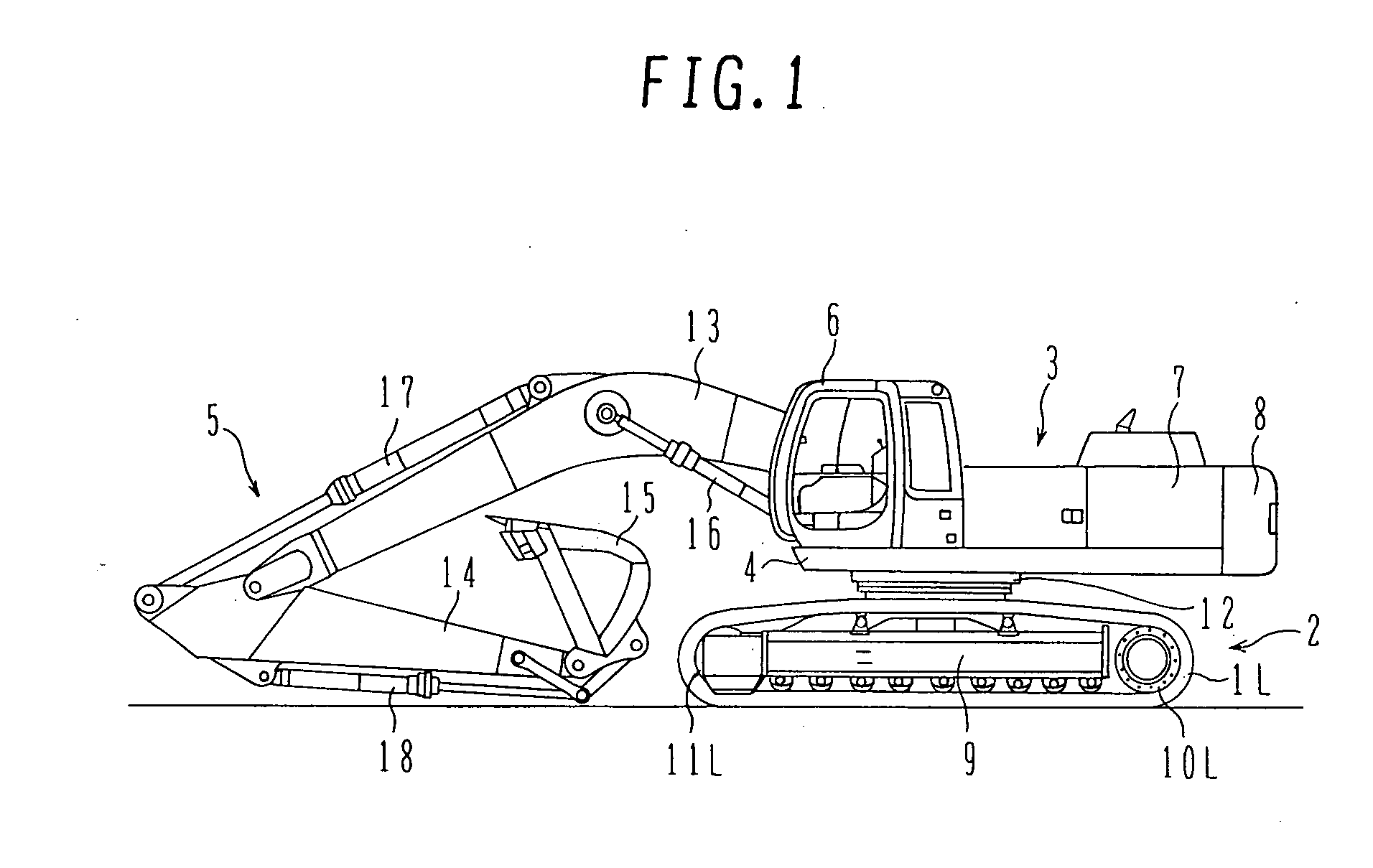
[0064]FIG. 1 is a side view showing an overall structure of a large-sized hydraulic excavator to which is applied the present invention. Note that, in the following description, the front side (left side in FIG. 1) looking from an operator, the rear side (right side in FIG. 1), the left side (side viewing the drawing sheet of FIG. 1), and the right side (side behind the drawing sheet of FIG. 1) when the operator sits on a cab seat with the hydraulic excavator being in a state shown in FIG. 1 are referred to simply as the “front side, rear side, left side, and right side”, respectively.

[0065]Referring to FIG. 1, the large-sized hydraulic excavator comprises a lower travel structure 2 including left and right caterpillar belts (crawlers) 1L, 1R (only 1L being shown in FIG. 1) which serve as traveling means, an upper swing body 3 installed on the lower travel structure 2 in a swingable manner, and a multi-a...

second embodiment

[0087]In this second embodiment, the cooling system further includes an air conditioner 40 for the cab, a condenser 41 for cooling a coolant of the air conditioner 40, a compressor 42 which is provided to be capable of being connected with and disconnected from an output shaft of the engine 19 and compresses the coolant introduced from the air conditioner 40 for supply to the condenser 41, and an open air temperature sensor 43 which is disposed between the air cleaner 39 and the turbo charger 38 and detects the temperature of open air. The condenser 41 is arranged upstream (left side in FIG. 7) of the radiator 23 and the oil cooler 24 in the direction of flow of the cooling air, and is arranged in side-by-side relation to the intercooler 22.

[0088]Though not shown in detail, the air conditioner 40 includes an operation switch capable of being manipulated by an operator, a blower for blowing cooled air into the cab, and a control unit for driving and controlling the compressor 42, the...

third embodiment

[0101]In this third embodiment, an engine revolution speed sensor 45 (engine revolution speed detecting means) for detecting the revolution speed of the engine 19 is provided and a detected signal from the sensor 45 is outputted to a controller 44A.

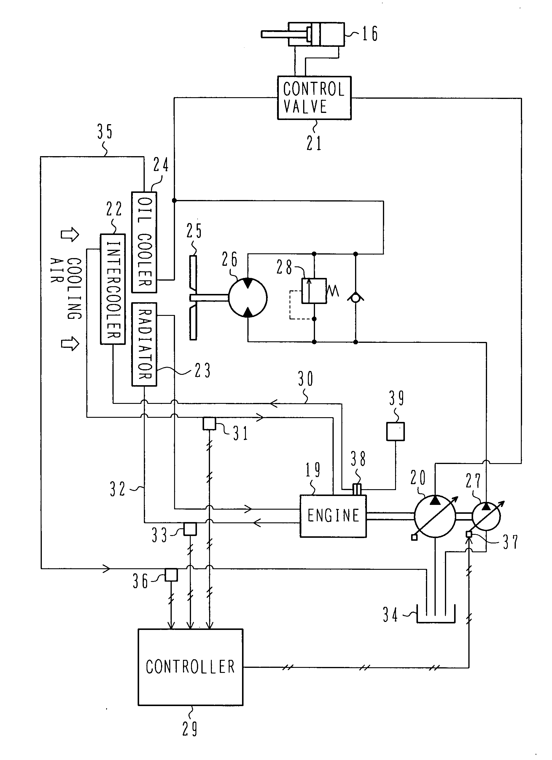
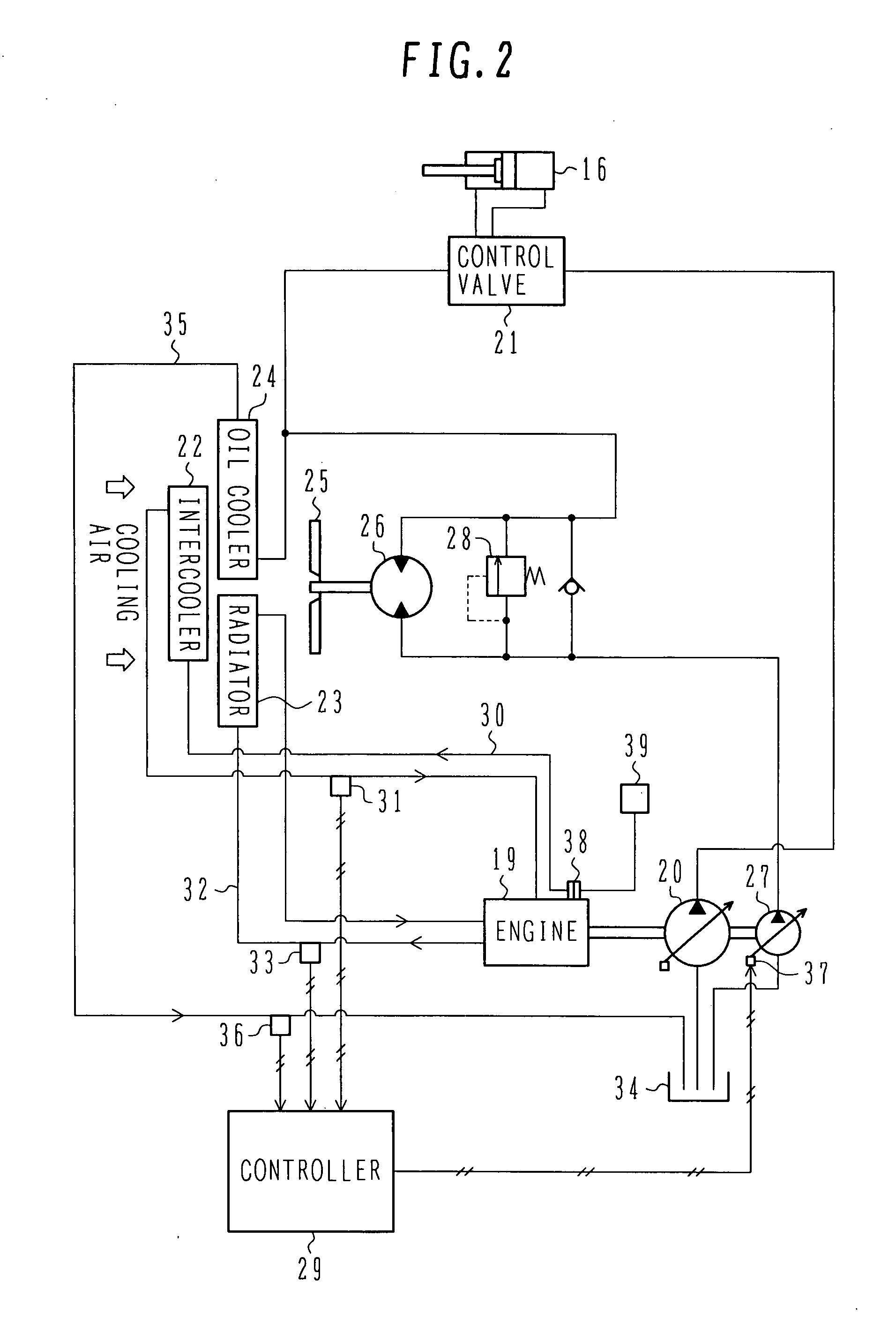
[0102]The controller 44A executes predetermined arithmetic and logical operations on the detected signals inputted from the air temperature sensor 31, the cooling water temperature sensor 33, the working oil temperature sensor 36, the open air temperature sensor 43, the engine revolution speed sensor 45, etc. based on operation tables (see FIGS. 4-6 and 9 described above and FIG. 12 described later for details) which have been set and stored in advance, and it outputs a produced control signal to the displacement control unit 37 for the fan hydraulic pump 27.

[0103]FIG. 11 is a flowchart showing procedures of control processing executed in the controller 44A, and FIG. 12 shows one of the operation tables stored in the controller 44A, the t...


PUM


Abstract

A cooling system for a construction machine, which can reduce noise of a cooling fan and can reliably produce cooling air at a required flow rate.
The cooling system comprises a cooling fan 25 for producing cooling air introduced to an intercooler 22, a radiator 23 and an oil cooler 24, a fan hydraulic motor 26 for driving the cooling fan 25, a fan hydraulic pump 27 for delivering a hydraulic fluid to the fan hydraulic motor 26, an air temperature sensor 31 for detecting an air temperature T1 at an outlet of the intercooler 22, a cooling water temperature sensor 33 for detecting a temperature T2 of cooling water for the radiator 23, a working oil temperature sensor 36 for detecting a temperature T3 of working oil for the oil cooler 24, and a controller 29 for outputting a control signal corresponding to a maximum value among calculation values N1, N2 and N3 of cooling fan rotation speed, which correspond respectively to detected values T1, T2 and T3 from the air temperature sensor 31, the cooling water temperature sensor 33 and the working oil temperature sensor 36.

Description

TECHNICAL FIELD[0001]The present invention relates to a construction machine such as a hydraulic excavator, and more particularly to a cooling system for a construction machine, which includes a cooling fan for producing cooling air introduced to heat exchangers such as an intercooler, a radiator, and an oil cooler.BACKGROUND ART[0002]In a construction machine, e.g., a hydraulic excavator, a front operating mechanism including a boom, an arm, a bucket, etc. and an upper swing body are operated by hydraulic actuators, e.g., a hydraulic cylinder and a hydraulic motor. Those hydraulic actuators are operated by a hydraulic fluid delivered from a hydraulic pump which is driven by an engine. The upper swing body is covered with a cover, and the engine and the hydraulic pump are disposed in an engine room formed within the cover. In that type of construction machine, it is usual that, for the purpose of cooling the engine, a cooling fan disposed in the engine room is driven to introduce op...

Claims


Application Information

Patent Timeline
Patent Type & Authority Applications(United States)
IPC IPC(8): G05D23/00F16D31/02F02B33/00F04B25/00
CPCF01P5/04F01P7/044F01P2060/04F01P2025/40F01P2025/13F01P7/04
Inventor YABUKI, YASUHISA
Owner NIHON KENKI CO LTD
Why Eureka
Try Eureka