Vacuum brazing technique of stainless steel plate fin structure

A technology of stainless steel plate and brazing process, applied in the direction of manufacturing tools, welding equipment, metal processing equipment, etc., can solve the problems of many structural defects and low strength, improve reliability, ensure brazing quality, and optimize vacuum brazing The effect of craft

Inactive Publication Date: 2009-03-25
NANJING UNIV OF TECH
View PDF1 Cites 44 Cited by
  • Summary
  • Abstract
  • Description
  • Claims
  • Application Information

AI Technical Summary

Problems solved by technology

[0004] The technical problem to be solved by the present invention is aimed at the disadvantages of many structural defects and low strength obtained in the prior art. On the basis of a large number of vacuum brazing, strength, microstructure observation and other tests, a suitable stainless steel plate is proposed. Vacuum brazing process of fin structure

Method used


Image

  • Vacuum brazing technique of stainless steel plate fin structure
  • Vacuum brazing technique of stainless steel plate fin structure
  • Vacuum brazing technique of stainless steel plate fin structure

Examples


Embodiment 1

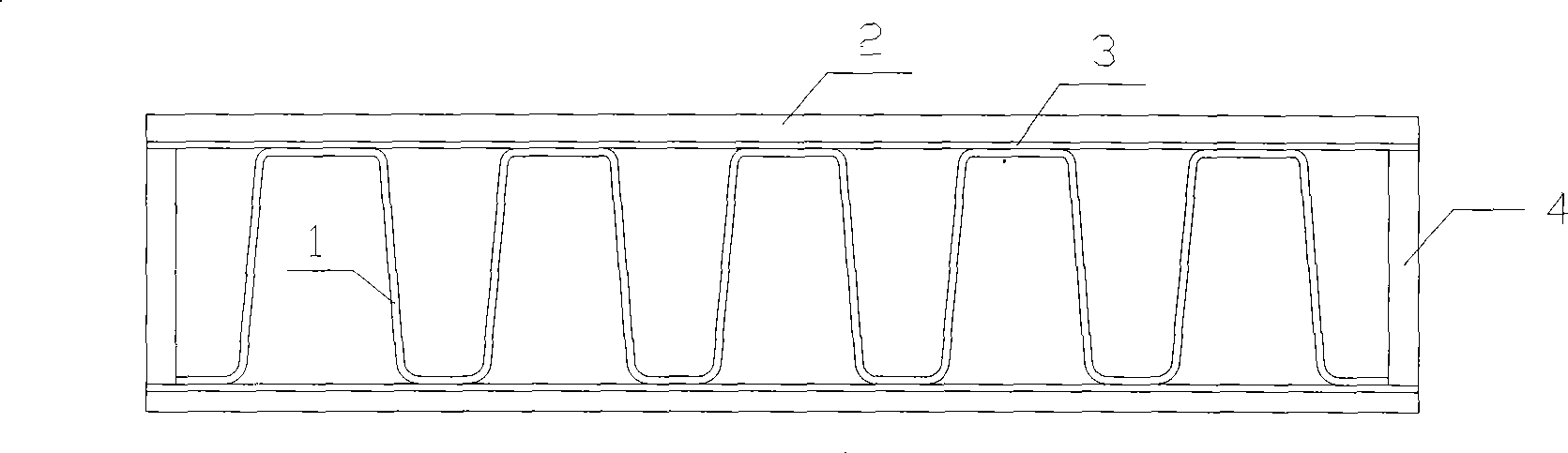
[0018] Embodiment 1: A stainless steel plate-fin structure is composed of fins (1), partitions (2), and seals (3). The material of the fins and the partitions are 304 stainless steel, the thickness of the fins is 0.2mm, and the thickness of the partitions is 0.4mm. The solder is nickel-based solder BNi2, and the thickness of the solder is 105 μm. First put a fin on the partition (metal flat plate), and then put a partition on it. The solder foil is preset between the fin and the partition, and then the two sides are sealed with edge seals to form a basic unit (such as figure 1 shown). Stack many basic units layer by layer, clamp firmly with the special brazing fixture designed by the inventor, apply a pressure of 5 MPa, put them into a vacuum brazing furnace, and use vacuum brazing to make a stainless steel plate-fin structure.

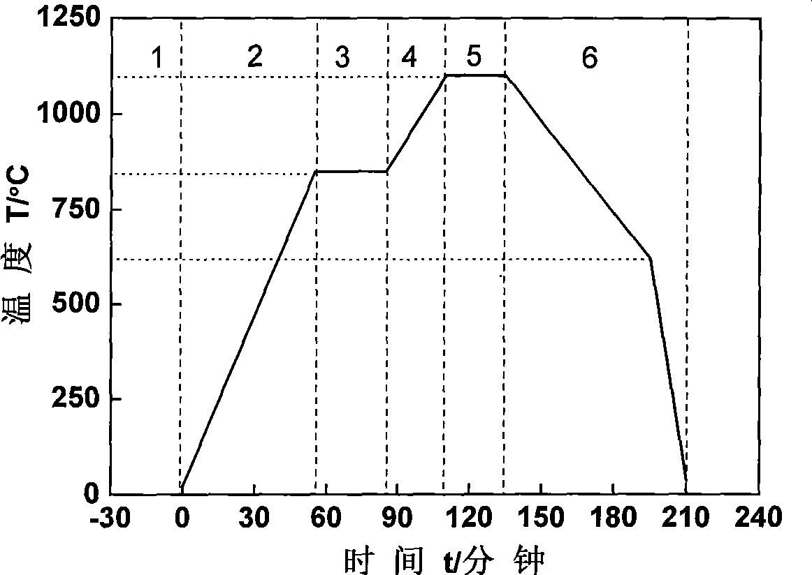
[0019] The vacuum brazing heating process consists of the following six steps:

[0020] The first step is the vacuum stage: the degree of vacuum ...

Embodiment 2

[0027] Embodiment 2: A stainless steel plate-fin structure, consisting of fins (1), partitions (2), and seals (3). The material of the fins and the partitions are 304 stainless steel, the thickness of the fins is 0.2mm, and the thickness of the partitions is 0.4mm. The solder is nickel-based solder BNi2, and the thickness of the solder is 110 μm. First put a fin on the partition (metal flat plate), and then put a partition on it. The solder foil is preset between the fin and the partition, and then the two sides are sealed with edge seals to form a basic unit (such as figure 1 shown). Stack many basic units layer by layer, clamp firmly with the special brazing fixture designed by the inventor, apply a pressure of 5 MPa, put them into a vacuum brazing furnace, and use vacuum brazing to make a stainless steel plate-fin structure.

[0028] The vacuum brazing heating process consists of the following six steps:

[0029] The first step is the vacuum stage: the degree of vacuum ...


PUM

PropertyMeasurementUnit
thicknessaaaaaaaaaa
tensile strengthaaaaaaaaaa

Abstract

The invention discloses a vacuum brazing process of a stainless steel plate-fin structure, comprising: firstly placing a fin on a baffle and then placing a baffle thereon, placing a solder foil between the fin and the baffles, and then sealing the two sides by edge sealing tapes to form an elementary unit; stacking up a plurality of elementary units according to the design requirements, then using a special jig to clamp and firm the units and exerting pressure on the units, and placing the units in a vacuum brazing furnace; vacuumizing the brazing furnace firstly; then heating the stainless steel plate-fin structure to 850 to 870DEG C and then preserving the heat; and again heating the stainless steel plate-fin structure to the brazing temperature of 1070 to 1100DEG C and then preserving the heat; and then self-cooling the structure slowly in vacuum from the brazing temperature of 1070 to 1100DEG C to 620 to 640DEG C, then filling nitrogen into the furnace, starting up a fan to cool the structure to 40 to 60DEG C so as to take out the structure, and finally obtaining the stainless steel plate-fin structure. The stainless steel plate-fin structure acquired through the brazing process has excellent microstructures and rather high strength.

Description

technical field [0001] The invention relates to a vacuum brazing process of a stainless steel plate-fin structure, belonging to the field of high-temperature-resistant stainless steel plate-fin heat exchangers. Background technique [0002] The stainless steel plate-fin structure is the core component of the stainless steel plate-fin heat exchanger, which is brazed by fins, partitions and seals. A metal flat plate (partition board) is placed at the upper and lower ends of the fins, and a solder foil is preset between the partition board, the fins and the seal. The melting point of the brazing filler metal is lower than that of the base metal, and the brazing filler metal alloy melts at the brazing temperature so that the fins, separators, and seals are welded into a whole. It has the characteristics of high thermal conductivity, small size, light weight, high temperature resistance, and high strength. It is used in high temperature and high pressure environments, such as ga...

Claims


Application Information

Patent Timeline
Patent Type & Authority Applications(China)
IPC IPC(8): B23K1/008
Inventor 蒋文春巩建鸣涂善东
Owner NANJING UNIV OF TECH
Why Eureka
Try Eureka