Potential difference meter

A technology of potentiometer and resistance, applied in the field of potentiometer, can solve the problems of complex structure of switch and instrument, increase of instrument volume, measurement data out of tolerance and so on

Inactive Publication Date: 2009-03-25
方宁妹
View PDF0 Cites 24 Cited by
  • Summary
  • Abstract
  • Description
  • Claims
  • Application Information

AI Technical Summary

Problems solved by technology

[0003] Since the second, third, fourth, and fifth stepping discs all have auxiliary discs, the number of layers of the switch is increased, thereby increasing the volume of the instrument, and also complicating the structure of the switch and the instrument, especially the instrument verification process. If the measurement data of the second, third, fourth, and fifth stepping discs are found to be out of tolerance, it is very troublesome to correct the inner layer resistance of the second, third, fourth, and fifth stepping disc switches

Method used


Image

  • Potential difference meter
  • Potential difference meter
  • Potential difference meter

Examples


Embodiment 1

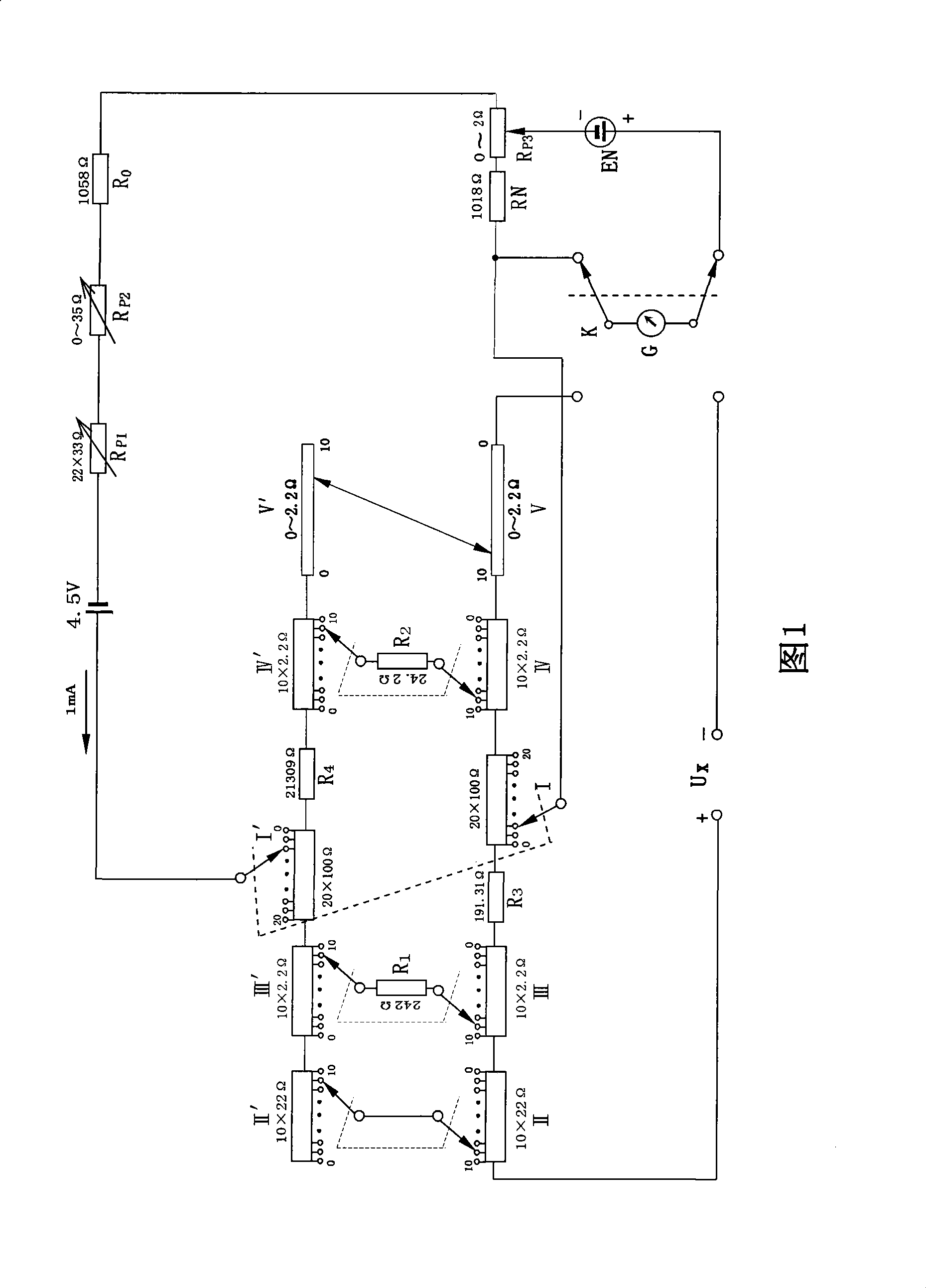
[0030] Example 1, in Figure 1, when the four stepping disks and one double-sliding wire disk are all set to "0", the resistance value on the left side between the two brushes of the first stepping disk is equal to 2334.31Ω, and the resistance value on the right side is equal to 23343.1 Ω, therefore, 10 / 11 of the total current between the two brushes of the first step disc flows on the left, and 1 / 11 flows on the right. When each step disc is placed with other contacts, the resistance added by the measuring disc in each step disc is equal to the resistance decreased by the replacement disc, so no matter what value is set on the four step discs and one double-slide disc, the first step The resistance values ​​on the left and right sides between the two brushes entering the plate remain unchanged.

[0031] The standard operating current of the potentiometer is 1mA, the left current between the two brushes of the first step plate is 10 / 11mA, and the right current is 1 / 11mA. The t...

Embodiment 2

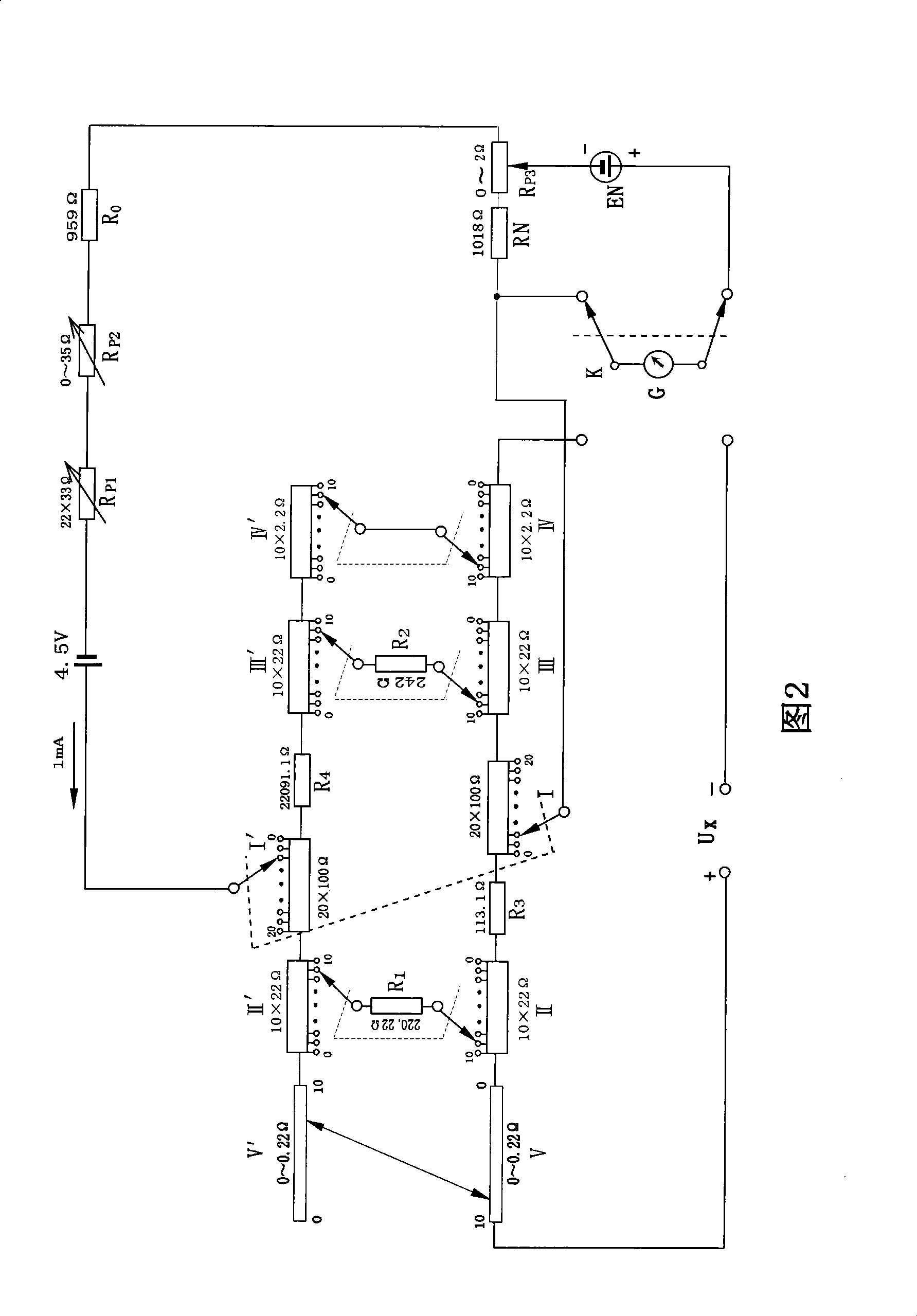
[0041] Embodiment 2, in Figure 2, when the four stepping disks and one double-sliding wire disk are all set to "0", the resistance on the left between the two brushes of the first stepping disk is equal to 2443.21Ω, and the resistance on the right is equal to 24432.1Ω, The total resistance between the two brushes of the first stepping disc is 2221.1Ω, so 10 / 11 of the total current between the two brushes of the first stepping disc flows on the left side, and 1 / 11 flows on the right side. When four stepping disks and one double-sliding wire disk are set to other indication values, the increased resistance of the measuring disk is equal to the reduced resistance of the replacement disk, so no matter what indication value is set on four stepping disks and one double-sliding wire disk, the first The resistance values ​​on the left and right sides between the two brushes of the stepping disk remain unchanged, and the total resistance of the circuit remains unchanged.

[0042]The st...

Embodiment 3

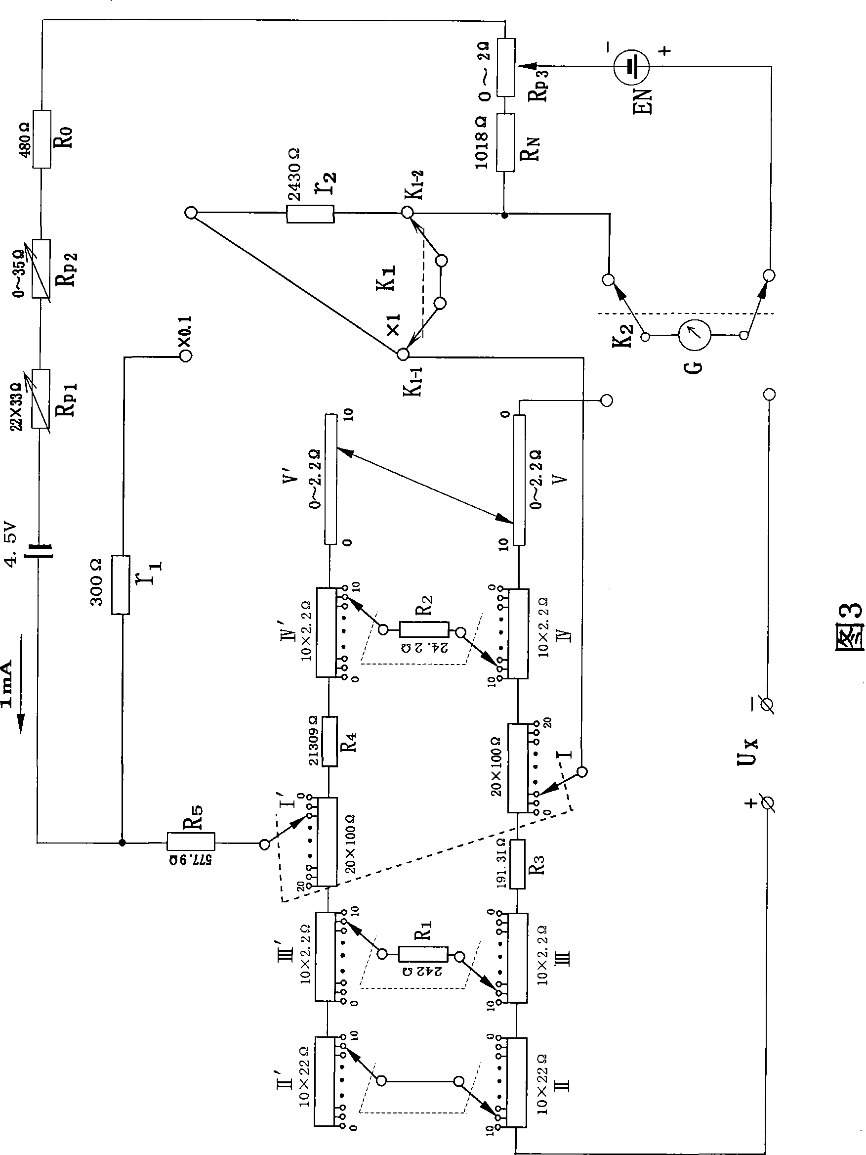
[0051] Embodiment 3, in Fig. 3, when the four stepping disks and one double sliding wire disk are all set to "0", the resistance value on the left side between the two brushes of the first stepping disk is equal to 2334.31Ω, and the resistance value on the right side is equal to 23343.1 Ω, therefore, 10 / 11 of the total current between the two brushes of the first step disc flows on the left, and 1 / 11 flows on the right. When each step disc is placed with other contacts, the resistance added by the measuring disc in each step disc is equal to the resistance decreased by the replacement disc, so no matter what value is set on the four step discs and one double-slide disc, the first step The resistance values ​​on the left and right sides between the two brushes entering the plate remain unchanged.

[0052] The standard operating current of the potentiometer is 1mA, the left current between the two brushes of the first step plate is 10 / 11mA, and the right current is 1 / 11mA. The ...


PUM


Abstract

The invention provides a potentiometer for measuring direct current voltage. The potentiometer comprises four step panels and a double wire sliding panel, the five panels consist of a measurement panel and a substitution panel with the same resistance value, working current is divided into two branches with the ration of ten to one between two electric brushes in the first step panel, and two panels of each branch are in parallel connection and have the same current; except the first step panel, electric brushes of measurement panels of other four step panels and the electric brush of the substitution panel are connected by resistors or conducting wires, neither each step panel nor the double wire sliding panel is provided with a bracket panel, thus the size of the instrument is reduced and the production cost is reduced. Meanwhile, the five measurement panels are connected through conducting wires, so the influence from deviation and thermoelectricity is eliminated.

Description

technical field [0001] The invention relates to an instrument for measuring DC voltage. Background technique [0002] Application numbers 2005100623569, 2005100622373, 2005100622585, etc. have disclosed a potentiometer with five stepping discs or a double-sliding line disc, and its second and third stepping discs are composed of a measuring disc, a substituting disc and an auxiliary disc. , the resistance value on the measuring disc is the same as that on the substituting disc, every time a resistance is increased on the measuring disc, the substituting disc will reduce the same resistance, when the second stepping disc is set at point 0, the second stepping disc and the third The resistances of the parallel parts of the step discs are equal, and when the third step discs are set with different indication values, the resistance of the circuit remains unchanged. When the second step disc is not set to "0", the third step disc is set to a different indication value, and the r...

Claims


Application Information

Patent Timeline
Patent Type & Authority Applications(China)
IPC IPC(8): G01R17/20
Inventor 方宁妹骆洪亮程军洪卓儿
Owner 方宁妹
Why Eureka
Try Eureka