Control method for three phase active electric power filter to output current wave
A power filter and output current technology, applied in active power filter, AC network to reduce harmonics/ripple, harmonic reduction device, etc. Simplify the circuit structure, improve the compensation effect, and improve the stability effect
- Summary
- Abstract
- Description
- Claims
- Application Information
AI Technical Summary
Problems solved by technology
Method used
Image
Examples
Embodiment
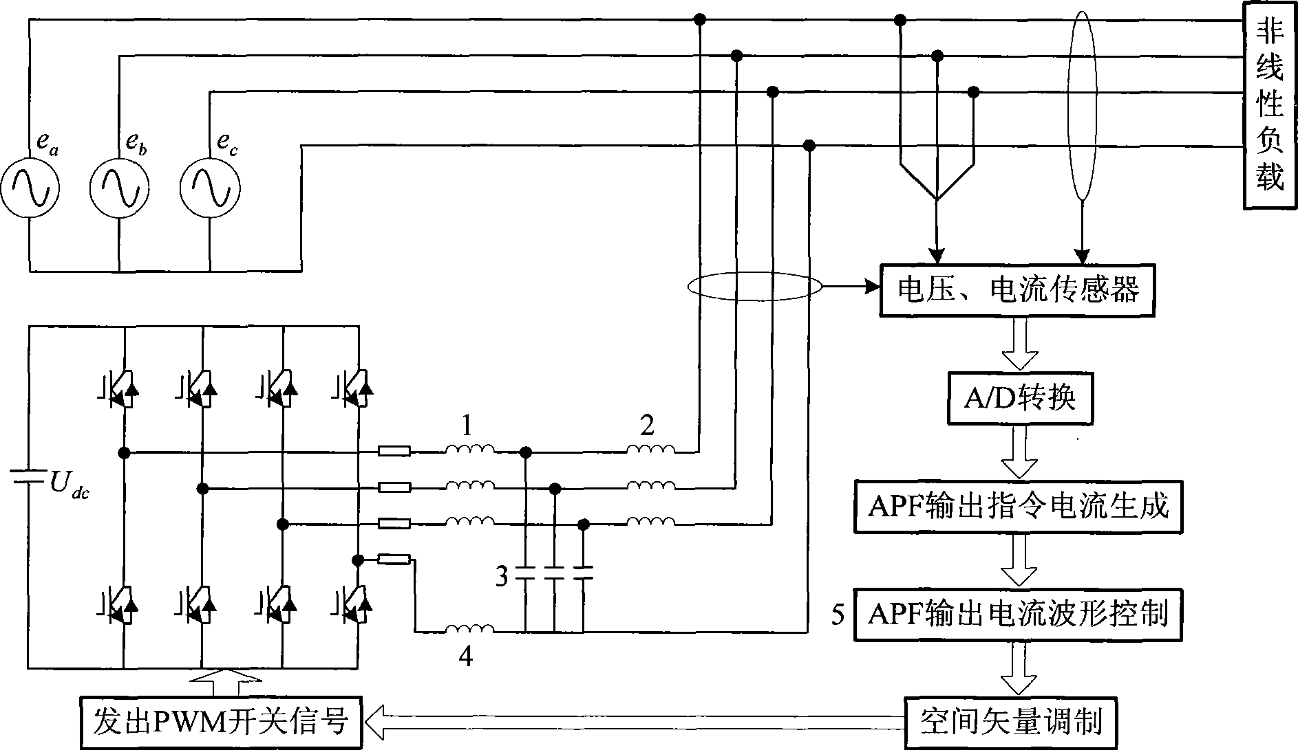
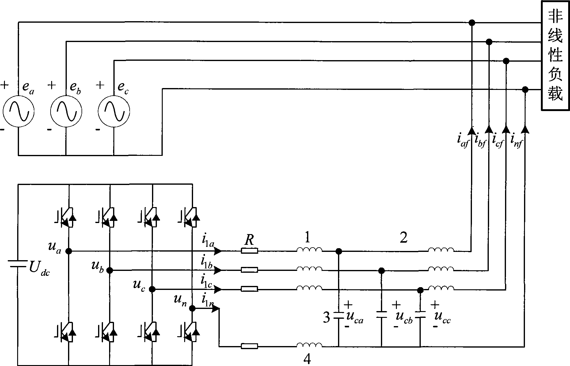
[0114] Embodiment: assume as image 3 The parameters of the first inductor 1, the second inductor 2, the first capacitor 3, and the third inductor 4 in the output filter of the active power filter under the 380V three-phase four-wire system are L 1 = 1mH, L 2 = 1mH, C 1 = 10μF, L n = 0.3mH, each bridge arm of the inverter output dead zone equivalent resistance R = 0.6Ω, the sampling time of the control system is 256 points per cycle, and the switching frequency is 6.4kHz.
[0115] For α and β phases, the state feedback matrix F calculated by formula (33) is [0.7871 -0.8252 0.0413], and the feedback matrix L of the state observer of the discrete system represented by formula (38) = [-0.1283 1.8598 5.1111], k=12 in the formula (27).
[0116] For phase 0, the state feedback matrix F calculated by formula (33) is [0.817 -0.8794 0.0606], and the feedback matrix L of the state observer of the discrete system represented by formula (38) = [0.4671 2.0531 9.3494], (27) In the form...
PUM
 Abstract
Description
Claims
Application Information
 - R&D
- Intellectual Property
- Life Sciences
- Materials
- Tech Scout
- Unparalleled Data Quality
- Higher Quality Content
- 60% Fewer Hallucinations
Browse by: Latest US Patents, China's latest patents, Technical Efficacy Thesaurus, Application Domain, Technology Topic, Popular Technical Reports.
© 2025 PatSnap. All rights reserved.Legal|Privacy policy|Modern Slavery Act Transparency Statement|Sitemap|About US| Contact US: help@patsnap.com


