Radio frequency power amplifier circuit

An amplifier circuit and amplifying circuit technology, applied in power amplifiers, high-frequency amplifiers, improving amplifiers to reduce temperature/power supply voltage changes, etc., can solve the problems of power amplifier output characteristics changes, limited temperature compensation, etc., to reduce dependence. , Enhance the effect of temperature compensation, improve stability and applicability

Active Publication Date: 2010-08-11
RDA TECH
View PDF0 Cites 3 Cited by
  • Summary
  • Abstract
  • Description
  • Claims
  • Application Information

AI Technical Summary

Problems solved by technology

[0004] However, this structure has no effect on the bias voltage V BIAS The change is very sensitive, and the compensation for temperature is limited. When the bias voltage fluctuates, it will cause a large change in the output characteristics of the power amplifier.

Method used


Image

  • Radio frequency power amplifier circuit
  • Radio frequency power amplifier circuit
  • Radio frequency power amplifier circuit

Examples


Embodiment Construction

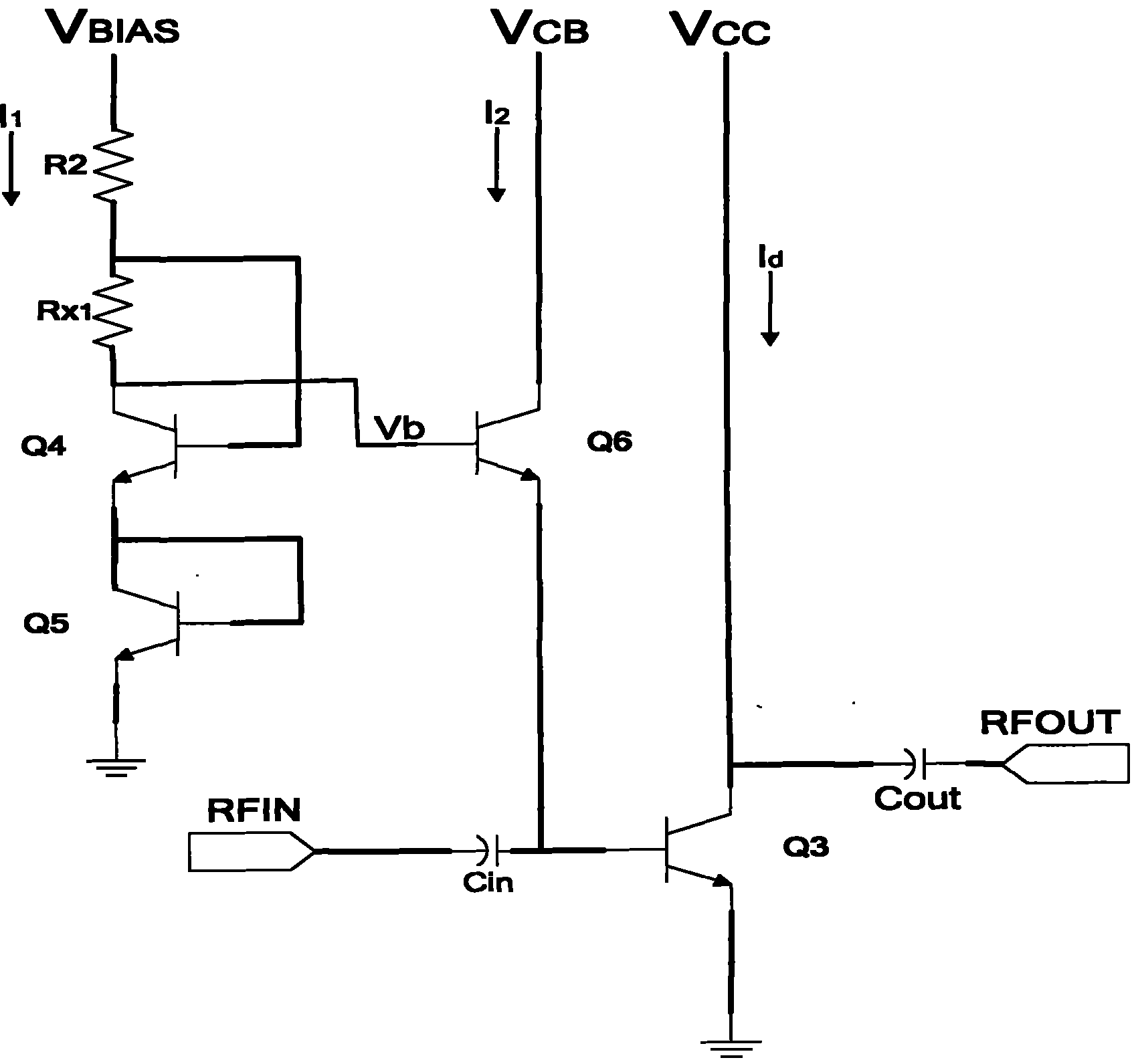
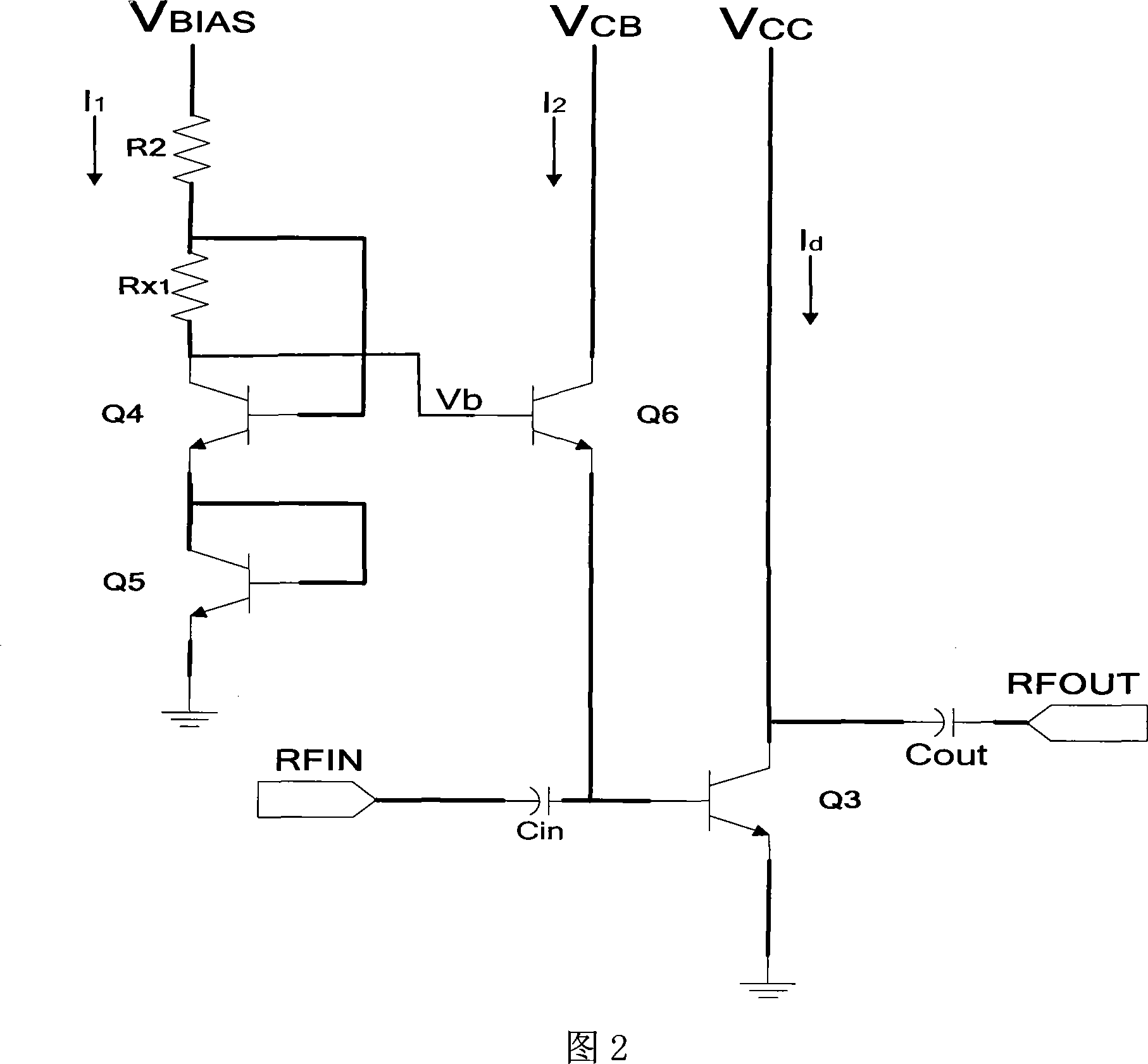
[0013] The radio frequency power amplifier circuit of the present invention, its circuit diagram as shown in Figure 2, comprises bias circuit and amplifying circuit, and described amplifying circuit comprises NPN tube Q3, and the emitter of described NPN tube Q3 is grounded, and the base of described NPN tube Q3 through a capacitor C in connected to the input signal, the collector of the NPN transistor Q3 is connected to the power supply terminal V CC , while passing through a capacitor C out Then as a signal output terminal, it is characterized in that the bias circuit includes three NPN transistors Q4, Q5 and Q6, and the collector of the NPN transistor Q4 is connected to the voltage bias terminal V BIAS There is a series connection between the resistor R2 and the compensating resistor R X1 , where resistor R2 is close to the voltage bias terminal V BIAS , compensation resistor R X1 Close to the collector of the NPN transistor Q4, the base of the NPN transistor Q4 is conn...


PUM


Abstract

The invention discloses a circuit of a radio-frequency power amplifier, which comprises a bias circuit and an amplification circuit. A resistance compensating structure is designed in the bias circuit, that is, a compensating resistance is added to the bias circuit. The added compensating resistance has two functions: (1) increasing the voltage compensation of the bias circuit and reducing the dependency of the circuit on the bias voltage; and (2) enhancing the temperature compensation of the bias circuit. The change of the bias voltage or temperature causes the electric current changes of Q4and Q5 or Q7 and Q8 of NPN tube, the change quantity of VBE of voltage generated by the electric current changes between a base electrode and a collector electrode can be compensated efficiently by the change quantity of two ends of R*1 or R*2, thereby ensuring the circuit is not sensitive to the bias voltage and the temperature.

Description

technical field [0001] The invention relates to an analog circuit, especially a radio frequency power amplifier circuit. Background technique [0002] In modern wireless communication systems, RF power amplifiers are key components for wireless transmission of RF signals. The main function of the RF power amplifier is to amplify the modulated RF signal to the required power value, transmit it to the antenna for transmission, and ensure that the receiver in a certain area can receive the signal. The performance of the radio frequency power amplifier circuit, which is a key part of the radio frequency part, has a direct impact on the communication quality. The RF power transistor is the core component of the RF power amplifier, and its working state is determined by the bias circuit, so the characteristics of the bias circuit directly affect the performance of the power amplifier. When the bias voltage is unstable or the junction voltage drop of the transistor changes due to...

Claims


Application Information

Patent Timeline
Patent Type & Authority Patents(China)
IPC IPC(8): H03F3/21H03F1/30H03F3/19
Inventor 陈俊谢利刚
Owner RDA TECH
Why Eureka
Try Eureka