
Exhaust system comprising catalysed soot filter

A technology of dust filter and exhaust system, which is applied in the direction of exhaust device, machine/engine, noise reduction device, etc., and can solve problems such as difficulty, impossibility of direct measurement, damage of thermocouple or filter, etc.

Active Publication Date: 2009-03-25
JOHNSON MATTHEY PLC
View PDF2 Cites 7 Cited by
  • Summary
  • Abstract
  • Description
  • Claims
  • Application Information

AI Technical Summary

Problems solved by technology

However, there is also the problem of accurately controlling the energy input to the CSF to avoid exposing the catalyst coating and filter substrate to detrimentally high temperatures, such as greater than 650°C, but ensuring that enough energy is introduced into the CSF to burn the PM
Thermocouples can be placed within the CSF itself in order to measure temperature, but this configuration has several drawbacks
First, the additional heat from the combustion of PM cannot be distinguished from the heat from the combustion of HC and / or CO in the exhaust gases, thus making direct measurement of the inlet gas state very difficult or virtually impossible
Second, there are durability issues associated with placing small diameter thermocouples within the CSF's compartment structure: either the thermocouple or the filter can be damaged

Method used


Image

  • Exhaust system comprising catalysed soot filter
  • Exhaust system comprising catalysed soot filter

Examples


Embodiment Construction

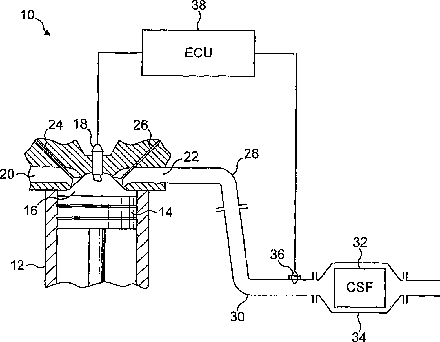
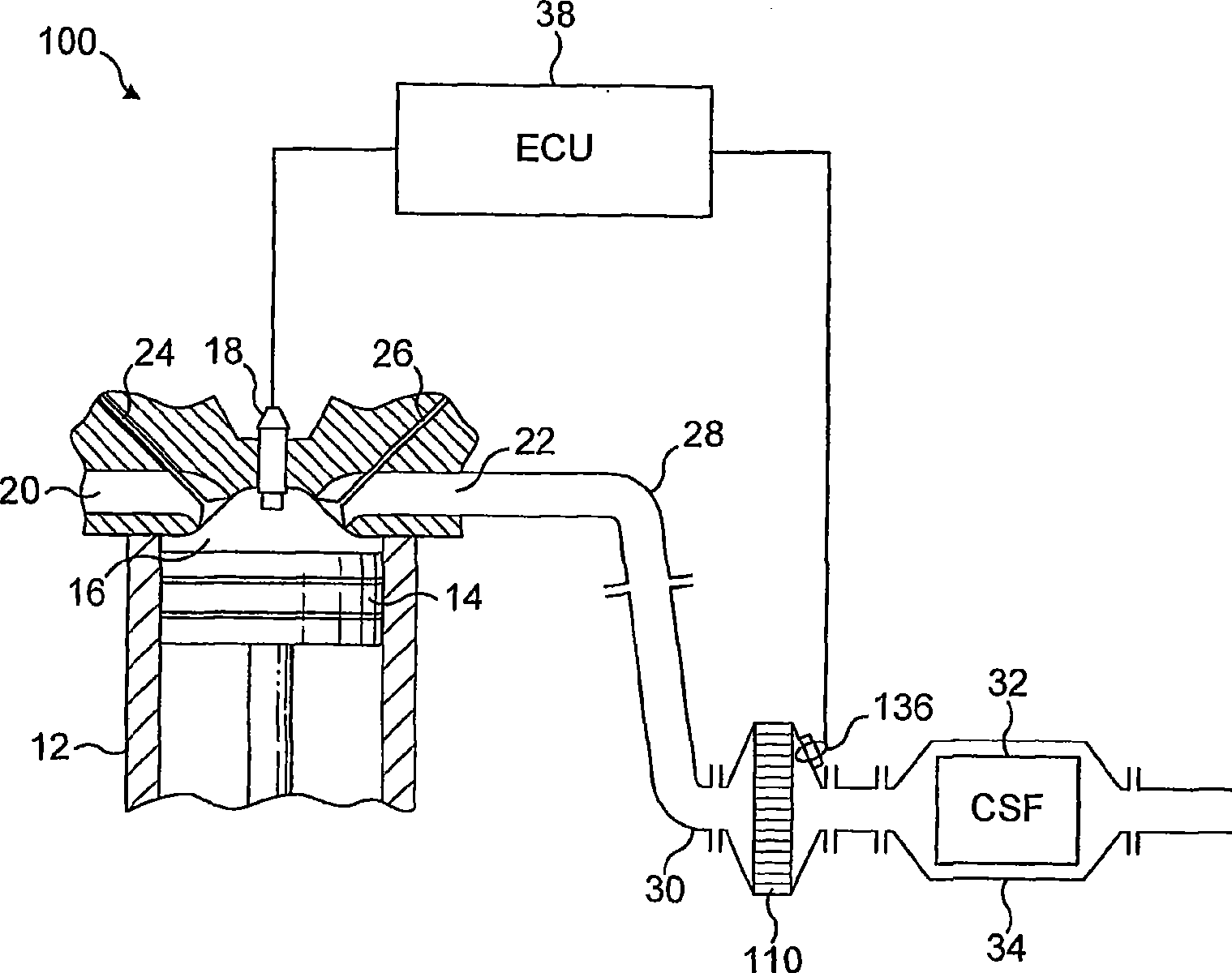
[0036] refer to figure 1 , the apparatus according to the invention is denoted by reference numeral 10, wherein 12 is a light diesel engine body, 14 is a piston, 16 is a combustion chamber, 18 is a conventional rail fuel injector, 20 is a suction port, 22 is a discharge port, 24 is a suction port Gas valve, 26 is a discharge valve, 28 is a discharge manifold, 30 is a discharge pipe, 32 is a CSF, 34 is a tank including a discharge gas diffuser to contain the CSF and keep it in communication with the discharge pipe, 36 is a sensor, including A catalyzed thermocouple junction and an uncatalyzed reference thermocouple junction, and 38 is an engine control unit (ECU) which, in use, is programmed to control common rail fuel injectors during active regeneration of the CSF in response to signals from Detection input of sensor 36.

[0037] In use, the ECU 38 determines the number of miles since the last active regeneration. When the mileage exceeds a predetermined amount, for example...


PUM


Abstract

An exhaust system for a lean burn internal combustion engine comprises: (a) a catalysed soot filter (CSF) (32); (b) a control unit (38); (c) means (18), controllable by the control unit, for 5 increasing a content of combustible hydrocarbon (HC) and / or carbon monoxide (CO) in an exhaust gas flowing into the CSF thereby to combust the HC and / or CO in the CSF, to increase the temperature of the CSFand to combust particulate matter collected thereon; and (d) catalysed sensor means (36) disposed between an engine manifold (28) and the CSF for combusting CO and / or HC in exhaust gas flowing in theexhaust system and inputting the control unit wit h a 10 datum correlat ing with an enthalpy of combustion of HC and / or CO in the exhaust gas, whereby the control unit, when in use, controls the combustible HC and / or CO introducing means in response to the datum input thereby to control the rate of contacting the CSF with combustible HC and / or CO.

Description

technical field [0001] The invention relates to an exhaust system for a lean-burn internal combustion engine, the exhaust system comprising a catalytic dust filter (CSF), a control unit and means controlled by the control unit in order to increase combustible hydrocarbons in the exhaust gas flowing to the CSF (HC) and / or carbon monoxide (CO) content, thereby burning HC and / or CO in the CSF, thereby increasing the temperature of the CSF and burning particulate matter (PM) collected thereon. Background technique [0002] It is known to use CSFs to meet regulatory exhaust gaseous emissions of PM, CO and HC in light duty diesel vehicles (as defined by relevant legislation). A known problem with using CSFs is that, for example during long periods of idle and / or slow driving conditions, the exhaust gas temperature is relatively cold, eg 150-200°C, and PM can accumulate on the CSF. Typically, this problem is overcome by employing means to actively regenerate the CSF, ie to activel...

Claims


Application Information

Patent Timeline
Patent Type & Authority Applications(China)
IPC IPC(8): F01N3/023F01N3/025
CPCF02D41/1444F01N3/035F01N13/02F02D2200/0804F01N3/0253F01N3/106F01N2560/022F01N2560/023F02D41/029F01N2340/00F01N2560/00F02D41/025F01N13/008F01N13/009F01N3/023F01N3/025
Inventor P·R·菲利普斯M·V·崔格
Owner JOHNSON MATTHEY PLC
Learn More